Chip information – Rainbow Electronics MAX5489 User Manual
Page 11
MAX5487/MAX5488/MAX5489
Dual, 256-Tap, Nonvolatile, SPI-Interface,
Linear-Taper Digital Potentiometers
______________________________________________________________________________________
11
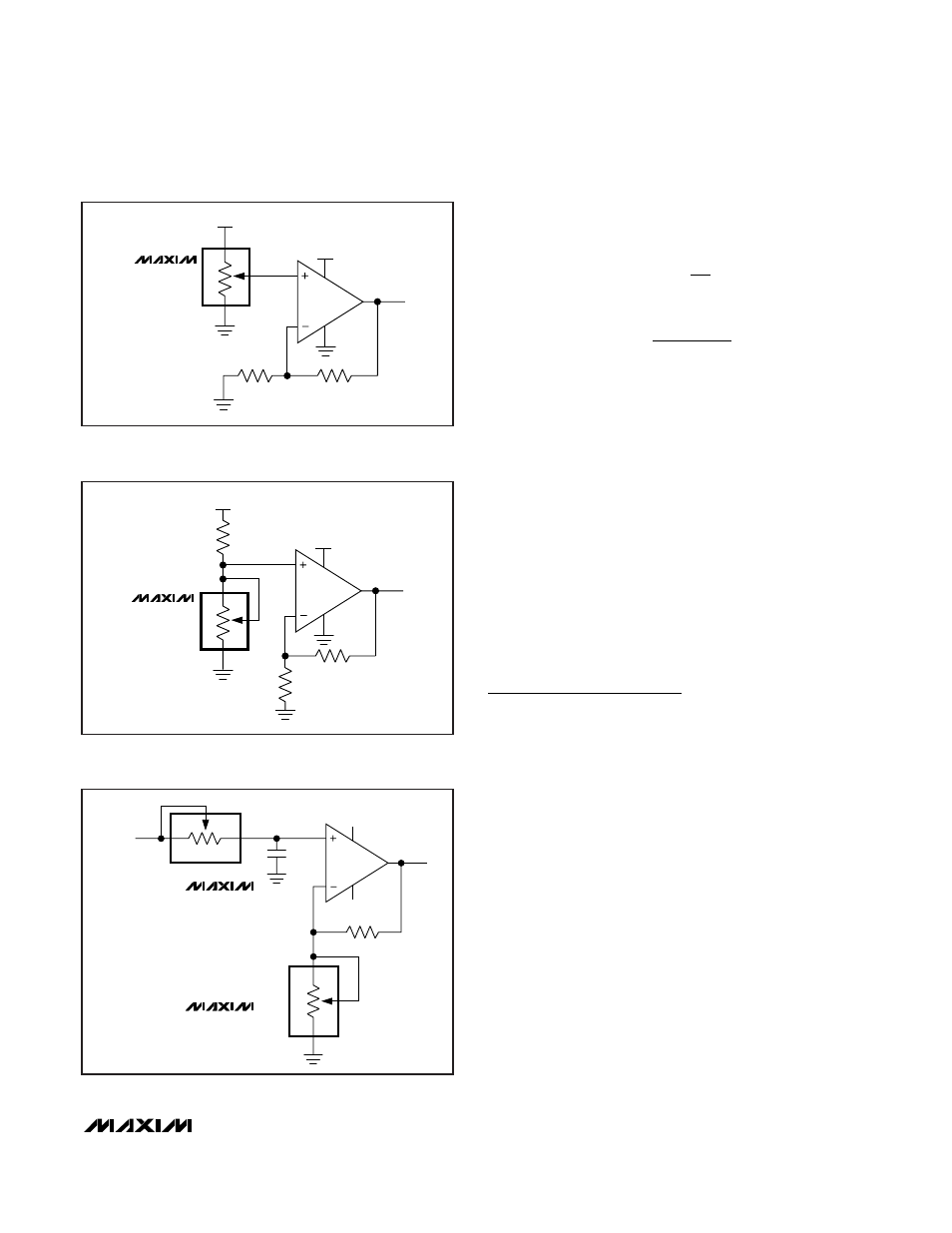
Use the following equations to calculate the gain (A)
and the -3dB cutoff frequency (f
C
):
Adjustable Voltage Reference
Figure 7 shows the MAX5487/MAX5488/MAX5489 used
as the feedback resistors in multiple adjustable volt-
age-reference applications. Independently adjust the
output voltages of the MAX6160s from 1.23V to V
IN
-
0.2V by changing the wiper positions of the MAX5487/
MAX5488/MAX5489.
Offset Voltage and Gain Adjustment
Connect the high and low terminals of one potentiome-
ter of a MAX5487/MAX5488/MAX5489 to the NULL
inputs of a MAX410, and connect the wiper to the op
amp’s positive supply to nullify the offset voltage over
the operating temperature range. Install the other
potentiometer in the feedback path to adjust the gain of
the MAX410 (see Figure 8).
Chip Information
TRANSISTOR COUNT: 12,177
PROCESS: BiCMOS
f
R
C
C
=
Ч
Ч
1
2
3
π
A
R
R
= +
1
1
2
Figure 4. Positive LCD-Bias Control Using a Voltage-Divider
V
OUT
30V
5V
W_
H_
L_
MAX5487
MAX5488
MAX5489
MAX480
Figure 5. Positive LCD-Bias Control Using a Variable Resistor
V
OUT
30V
5V
W_
H_
L_
MAX5487
MAX5488
MAX5489
MAX480
Figure 6. Programmable Filter
1/2 MAX5487
1/2 MAX5488
1/2 MAX5489
1/2 MAX5487
1/2 MAX5488
1/2 MAX5489
V
IN
R
2
HB
WB
LB
R
1
V
OUT
R
3
HA
WA
LA
C
MAX410
V+
V-
R
2
, R
3
= R
HL
x D / 256
WHERE R
HL
= END-TO-END RESISTANCE
AND D = DECIMAL VALUE OF WIPER CODE