Pin description – Rainbow Electronics MAX7358 User Manual
Page 8
MAX7356/MAX7357/MAX7358
1-to-8 I
2
C Bus Switches/Multiplexers with Bus
Lock-Up Detection, Isolation, and Notification
8
_______________________________________________________________________________________
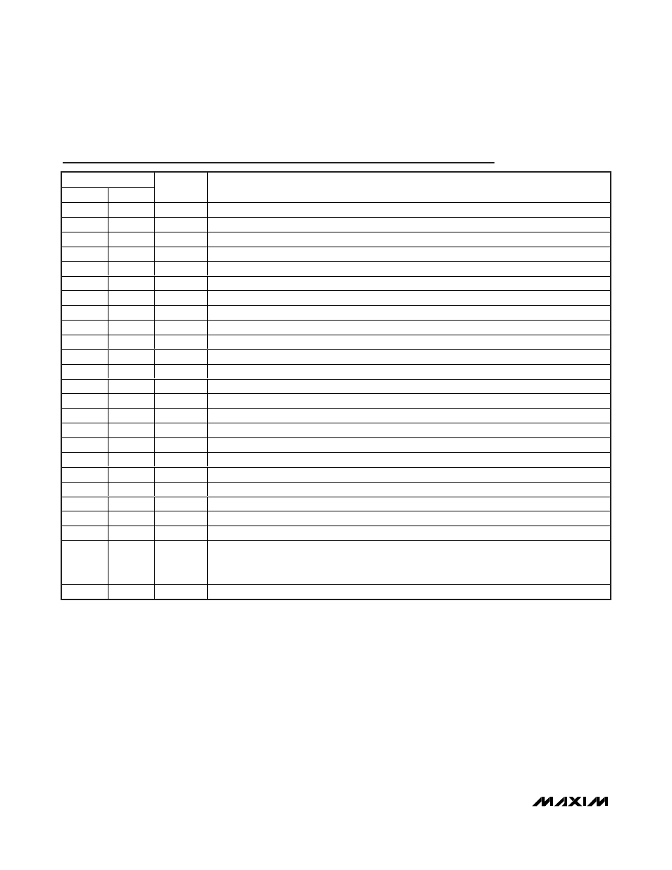
Pin Description
PIN
TQFN
TSSOP
NAME
FUNCTION
1
4
SD0
I
2
C Bus0 Serial Data
2
5
SC0
I
2
C Bus0 Serial Clock
3
6
SD1
I
2
C Bus1 Serial Data
4
7
SC1
I
2
C Bus1 Serial Clock
5
8
SD2
I
2
C Bus2 Serial Data
6
9
SC2
I
2
C Bus2 Serial Clock
7
10
SD3
I
2
C Bus3 Serial Data
8
11
SC3
I
2
C Bus3 Serial Clock
9
12
GND
Supply Ground
10
13
SD4
I
2
C Bus4 Serial Data
11
14
SC4
I
2
C Bus4 Serial Clock
12
15
SD5
I
2
C Bus5 Serial Data
13
16
SC5
I
2
C Bus5 Serial Clock
14
17
SD6
I
2
C Bus6 Serial Data
15
18
SC6
I
2
C Bus6 Serial Clock
16
19
SD7
I
2
C Bus7 Serial Data
17
20
SC7
I
2
C Bus7 Serial Clock
18
21
A2
Device Address Bit 2
19
22
SCL
Main I
2
C Bus Clock
20
23
SDA
Main I
2
C Bus Data
21
24
V
DD
Supply Voltage
22
1
A0
Device Address Bit 0
23
2
A1
Device Address Bit 1
24
3
RST
(RST/INT)
Active-Low Reset Input and Interrupt Output. RST resets the MAX7356 by a host. RST/INT on
the MAX7357 or MAX7358 is bidirectional. RST/INT is used to reset the device by a host or by
the device to send an interrupt signal to the host.
—
—
EP
E xp osed P ad ( TQ FN O nl y) . C onnect E P to g r ound . D o not use E P as the onl y g r ound connecti on.
( ) For the MAX7357/MAX7358 only.