Table 6. lock-up register channel indication – Rainbow Electronics MAX7358 User Manual
Page 15
MAX7356/MAX7357/MAX7358
1-to-8 I
2
C Bus Switches/Multiplexers with Bus
Lock-Up Detection, Isolation, and Notification
______________________________________________________________________________________
15
tion exists on that channel. If the interrupt feature is
selected (B0 of the configuration register is 1), howev-
er, the interrupt signal, RST/INT, deasserts (goes to
high) once this bus lock-up indication register is read.
If desired, setting bit B3 of the configuration register to
1 can latch the lock-up data. When B3 is set, the lock-
up bits remain set (even if a channel becomes
“unstuck”) until the lock-up indication register is read
by the master. Lock-up conditions on unconnected aux-
iliary buses are also detected. When this happens, oper-
ation is the same as when lock-ups are detected on
connected buses, except that, if desired, bus connec-
tions may be maintained as long as any detected lock-
ups are present only on unconnected channels. This
option is selected using bit B4 of the configuration regis-
ter. (Figure 9)
Traffic Prior to Lock-Up Register
(MAX7357/MAX7358)
The I
2
C bus traffic information per SCL clock is moni-
tored and stored into the two-byte traffic prior to lock-up
register. The first two bytes of information after a START
are stored in this register. This I
2
C bus traffic informa-
tion is frozen upon a bus lock-up detection. A host can
read these two bytes of traffic information upon the
reception of an interrupt signal. The contents of the traf-
fic prior to lock-up register is released and refreshed
once it is read.
The traffic prior to lock-up register can be used to iden-
tify the device address as well as the following byte
involved in a bus lock-up.
When troubleshooting an I
2
C bus, a scope is usually
used to capture traffic leading to the problem. The con-
tents of the traffic prior to the bus fault can usually be
determined by identifying a device address, a register
address, or a part of this data.
Table 7 shows contents of the traffic prior to the lock-up
register corresponding to a lock-up situation as demon-
strated by Figure 10.
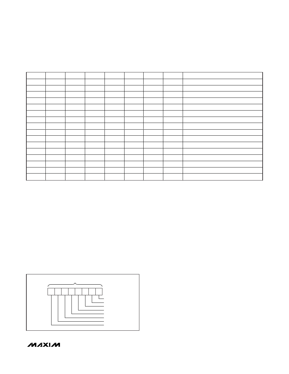
Figure 9. Lock-Up Indication Bits
B7
B6
B5
B4
B3
B2
B1
B0
COMMAND
X
X
X
X
X
X
X
0
Channel 0 no lock-up
X
X
X
X
X
X
X
1
Channel 0 lock-up
X
X
X
X
X
X
0
X
Channel 1 no lock-up
X
X
X
X
X
X
1
X
Channel 1 lock-up
X
X
X
X
X
0
X
X
Channel 2 no lock-up
X
X
X
X
X
1
X
X
Channel 2 lock-up
X
X
X
X
0
X
X
X
Channel 3 no lock-up
X
X
X
X
1
X
X
X
Channel 3 lock-up
X
X
X
0
X
X
X
X
Channel 4 no lock-up
X
X
X
1
X
X
X
X
Channel 4 lock-up
X
X
0
X
X
X
X
X
Channel 5 no lock-up
X
X
1
X
X
X
X
X
Channel 5 lock-up
X
0
X
X
X
X
X
X
Channel 6 no lock-up
X
1
X
X
X
X
X
X
Channel 6 lock-up
0
X
X
X
X
X
X
X
Channel 7 no lock-up
1
X
X
X
X
X
X
X
Channel 7 lock-up
Table 6. Lock-Up Register Channel Indication
X = Don’t care.
B6
B0
B7
B5
B4
B3
B2
B1
CHANNEL LOCK-UP INDICATION BITS (READ)
CHANNEL 0
CHANNEL 1
CHANNEL 2
CHANNEL 3
CHANNEL 4
CHANNEL 5
CHANNEL 6
CHANNEL 7