Electrical characteristics (continued) – Rainbow Electronics MAX17000 User Manual
Page 7
MAX17000
Complete DDR2 and DDR3 Memory
Power-Management Solution
_______________________________________________________________________________________
7
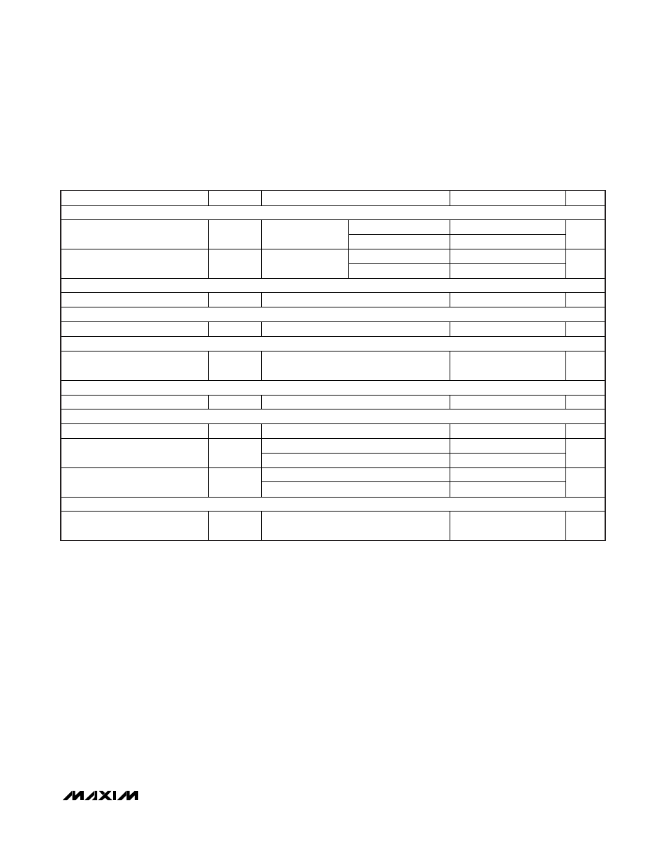
ELECTRICAL CHARACTERISTICS (continued)
(V
IN
= 12V, V
CC
= V
DD
= V
SHDN
= V
REFIN
= 5V, V
CSL
= 1.8V, STDBY = SKIP = AGND, T
A
= -40°C to +85°C, unless otherwise noted.)
(Note 1)
PARAMETER
SYMBOL
CONDITIONS
MIN
MAX
UNITS
REFERENCE BUFFER (VTTR)
I
VTT
= ±1mA
-10
+10
VTTR Output Accuracy (Adj)
REFIN to VTTR
I
VTT
= ±3mA
-20
+20
mV
I
VTT
= ±1mA
-10
+10
VTTR Output Accuracy (Preset)
V
CSL
/2 to VTTR
I
VTT
= ±3mA
-20
+20
mV
FAULT DETECTION (SMPS)
PGOOD1 Output Low Voltage
I
SINK
= 3mA
0.4
V
FAULT DETECTION (VTT)
PGOOD2 Output Low Voltage
I
SINK
= 3mA
0.4
V
FAULT DETECTION
V
CC
Undervoltage-Lockout
Threshold
V
UVLO(VCC)
Rising edge, IC disabled below this level;
hysteresis = 200mV
4.0 4.4 V
CURRENT LIMIT
Valley Current-Limit Threshold
V
LIMIT
V
CSH
- V
CSL
15 25
mV
SMPS GATE DRIVERS
DH Gate Driver On-Resistance
R
DH
BST - LX forced to 5V
5
DL high
5
DL Gate Driver On-Resistance
R
DL
DL low
3
DL rising
10
Dead Time
t
DEAD
DL falling
15
ns
INPUTS AND OUTPUTS
Logic Input Threshold
SHDN, STDBY, SKIP OVP, rising edge
hysteresis = 300mV/600mV (min/max)
1.3 2 V
Note 1: Limits are 100% production tested at T
A
= +25°C. Maximum and minimum limits over temperature are guaranteed by design
and characterization.
Note 2: On-time and off-time specifications are measured from 50% point at the DH pin with LX = GND, V
BST
= 5V, and a 250pF
capacitor connected from DH to LX. Actual in-circuit times might differ due to MOSFET switching speeds.