Design procedure – Rainbow Electronics MAX17000 User Manual
Page 23
MAX17000
Complete DDR2 and DDR3 Memory
Power-Management Solution
______________________________________________________________________________________
23
SMPS Overvoltage Protection (OVP)
If the output voltage of the SMPS rises 115% above its
nominal regulation voltage while OVP is enabled (OVP
= V
CC
), the controller sets its overvoltage fault latch,
pulls PGOOD1 and PGOOD2 low, and forces DL high.
The VTT and VTTR block shut down immediately, and
the internal 16
Ω discharge MOSFETs on CSL and VTT
are turned on. If the condition that caused the overvolt-
age persists (such as a shorted high-side MOSFET),
the battery fuse blows. Cycle V
CC
below 1V or toggle
SHDN to clear the overvoltage fault latch and restart the
controller.
OVP is disabled when OVP is connected to GND (Table
4). PGOOD1 upper threshold remains active at 115% of
nominal regulation voltage even when OVP is disabled,
and the 16
Ω discharge MOSFETs on CSL and VTT are
not enabled in shutdown.
SMPS Undervoltage Protection (UVP)
If the output voltage of the SMPS falls below 85% of its
regulation voltage for more than 200μs (typ), the controller
sets its undervoltage fault latch, pulls PGOOD1 and
PGOOD2 low, and begins soft-shutdown pulsing DL. DH
remains off during the soft-shutdown sequence initiated
by an undervoltage fault. After soft-shutdown has com-
pleted, the MAX17000 forces DL and DH low, and
enables the internal 16
Ω discharge MOSFETs on CSL
and VTT. Cycle V
CC
below 1V or toggle SHDN to clear
the undervoltage fault latch and restart the controller.
VTT Overvoltage and Undervoltage Protection
If the output voltage of the VTT regulator exceeds
±10% of its regulation voltage for more than 5ms (typ),
the controller sets its fault latch, pulls PGOOD1 and
PGOOD2 low, and begins soft-shutdown pulsing DL.
DH remains off during the soft-shutdown sequence initi-
ated by an undervoltage fault. After soft-shutdown has
completed, the MAX17000 forces DL and DH low, and
enables the internal 16
Ω discharge MOSFETs on CSL
and VTT. Cycle V
CC
below 1V or toggle SHDN to clear
the undervoltage fault latch and restart the controller.
Thermal-Fault Protection
The MAX17000 features a thermal-fault protection cir-
cuit. When the junction temperature rises above
+160°C, a thermal sensor activates the fault latch, pulls
PGOOD1 and PGOOD2 low, and shuts down using the
shutdown sequence. Toggle SHDN or cycle V
CC
power
below V
CC
POR to reactivate the controller after the
junction temperature cools by 15°C.
Design Procedure
Firmly establish the input voltage range and maximum
load current before choosing a switching frequency and
inductor operating point (ripple-current ratio). The pri-
mary design trade-off lies in choosing a good switching
frequency and inductor operating point, and the follow-
ing four factors dictate the rest of the design:
•
Input Voltage Range: The maximum value
(V
IN(MAX)
) must accommodate the worst-case input
supply voltage allowed by the notebook’s AC
adapter voltage. The minimum value (V
IN(MIN)
)
must account for the lowest input voltage after
drops due to connectors, fuses, and battery selec-
tor switches. If there is a choice at all, lower input
voltages result in better efficiency.
•
Maximum Load Current: There are two values to
consider. The peak load current (I
LOAD(MAX)
) deter-
mines the instantaneous component stresses and
filtering requirements, and thus drives output
capacitor selection, inductor saturation rating, and
the design of the current-limit circuit. The continu-
ous load current (I
LOAD
) determines the thermal
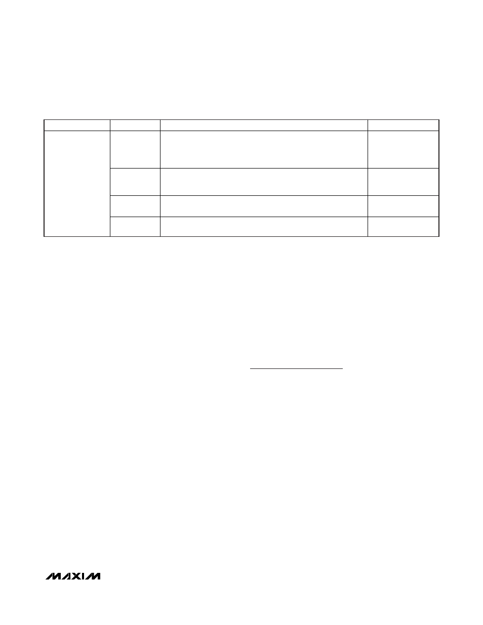
OVP
MODE
REACTION/DRIVER STATE
COMMENT
Thermal fault
DL and DH immediately pulled low.
PGOOD1 and PGOOD2 immediately forced low.
VTT and VTTR blocks immediately disabled (high impedance, no
16
discharge on outputs).
Active-fault condition.
V
CC
UVLO
rising edge
Activate INT_REF once V
CC
rises above UVLO, and
SHDN = high.
Once REFOK is valid (high), initiate the soft-start sequence.
DL remains low until switching/soft-start begins.
—
V
CC
POR
rising edge
DL forced low.
—
General Shutdown
and Fault
Conditions
V
CC
POR
falling edge
DL = Don’t care. V
CC
less than 2VT is not sufficient to turn on the
MOSFETs.
—
Table 4. Fault Protection and Shutdown Setting Truth Table (continued)