Rainbow Electronics MAX17000 User Manual
Page 19
MAX17000
Complete DDR2 and DDR3 Memory
Power-Management Solution
______________________________________________________________________________________
19
The MAX17000 always uses skip mode during startup,
regardless of the SKIP and STDBY setting. The SKIP
and STDBY controls take effect after soft-start is done.
See Figure 3.
Forced-PWM Mode (
SKIP = V
CC
)
The low-noise forced-PWM mode (SKIP = V
CC
) disables
the zero-crossing comparator, which controls the low-
side switch on-time. This forces the low-side gate-drive
waveform to constantly be the complement of the high-
side gate-drive waveform, so the inductor current
reverses at light loads while DH maintains a duty factor
of V
OUT
/V
IN
. The benefit of forced-PWM mode is to keep
a fairly constant switching frequency. However, forced-
PWM operation comes at a cost: the no-load 5V bias
current remains between 2mA to 20mA, depending on
the switching frequency.
STDBY = AGND overrides the SKIP pin setting, forcing
the MAX17000 into standby.
The MAX17000 switches to forced-PWM mode during
shutdown, regardless of the state of SKIP and STDBY
levels.
Standby Mode (
STDBY)
It should be noted that standby mode in the MAX17000
corresponds to computer system standby operation,
and is not referring to the MAX17000 shutdown status.
When standby mode is enabled (STDBY = AGND), the
MAX17000 switches over from the fast internal PWM
block to a low-quiescent current mode using a low-
power valley comparator to initiate an on-time pulse.
The zero-crossing comparator is enabled so that the
MAX17000 only operates in discontinuous mode,
reducing the maximum available output current by 1/6.
The system is NOT expected to have any fast load tran-
sients in such a state. While in standby, VTT is disabled
(high impedance) but VTTR remains active. SKIP is
ignored when standby mode is enabled.
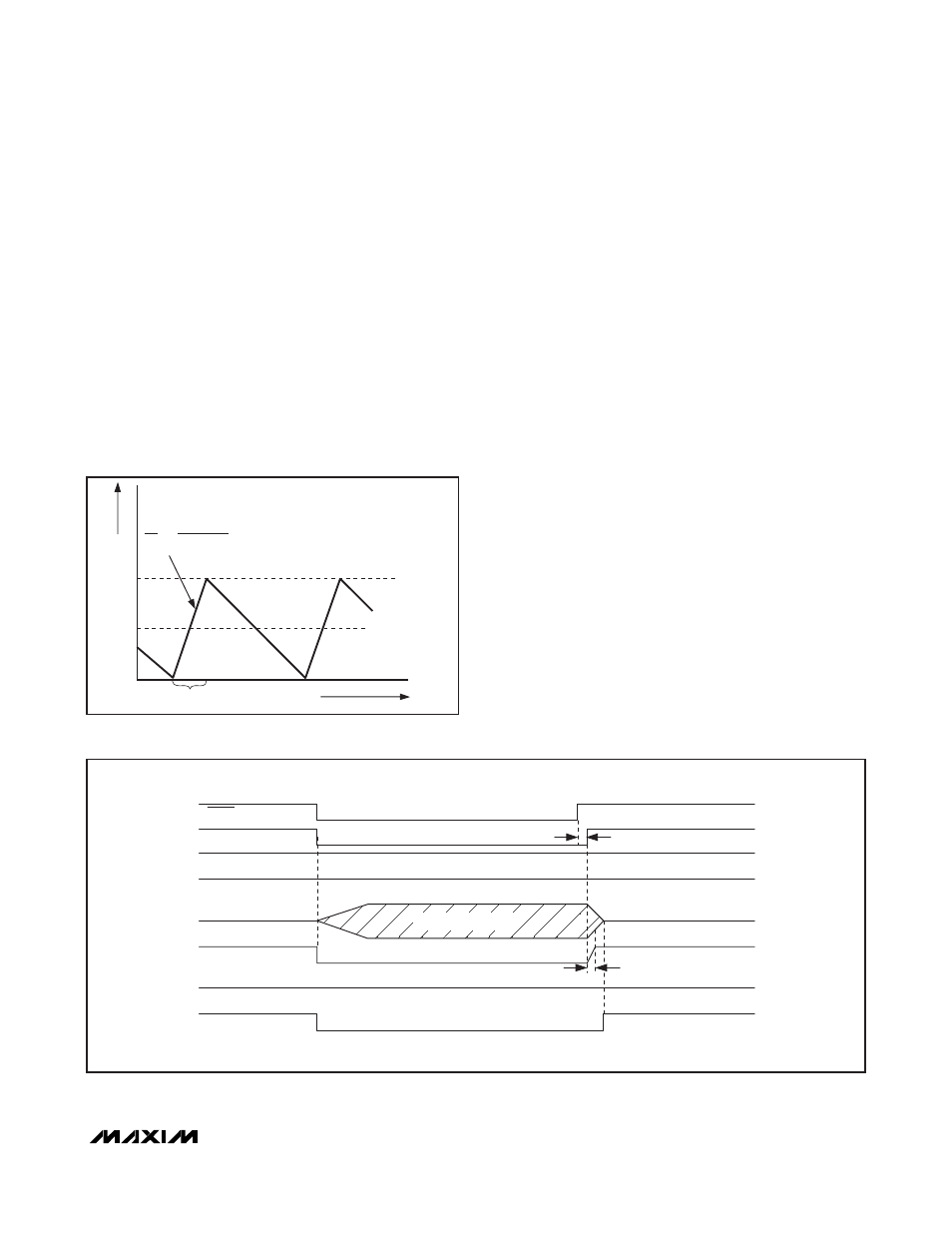
When standby mode is disabled (STDBY = V
CC
), the
MAX17000 reenables its fast internal PWM block. Once
the internal SMPS block is ready, the VTT block is
enabled and the VTT output capacitor is charged. The
VTT soft-start current limit increases linearly from zero
to its maximum current limit in 160μs (typ), keeping the
input VTTI inrush low. See Figure 4.
INDUCTOR CURRENT
I
LOAD
= I
PEAK
/2
ON-TIME
0
TIME
I
PEAK
L
V
IN
- V
OUT
ΔI
Δt
=
Figure 3. Pulse-Skipping/Discontinuous Crossover Point
STDBY
SMPS OUTPUT
SMPS_RUNOK
PGOOD1
VTT OUTPUT
VTT CURRENT LIMIT
PGOOD2
160
μs
VTT HIGH IMPEDANCE
< 50
μs
VTTR OUTPUT
Figure 4. MAX17000 Standby Mode Timing