Rf-tvml70 tv wall mount, You’ll need – RocketFish RF-TVML70 - User Manual User Manual
Page 13
13
Need help? Call 800-620-2790
RF-TVML70 TV Wall Mount
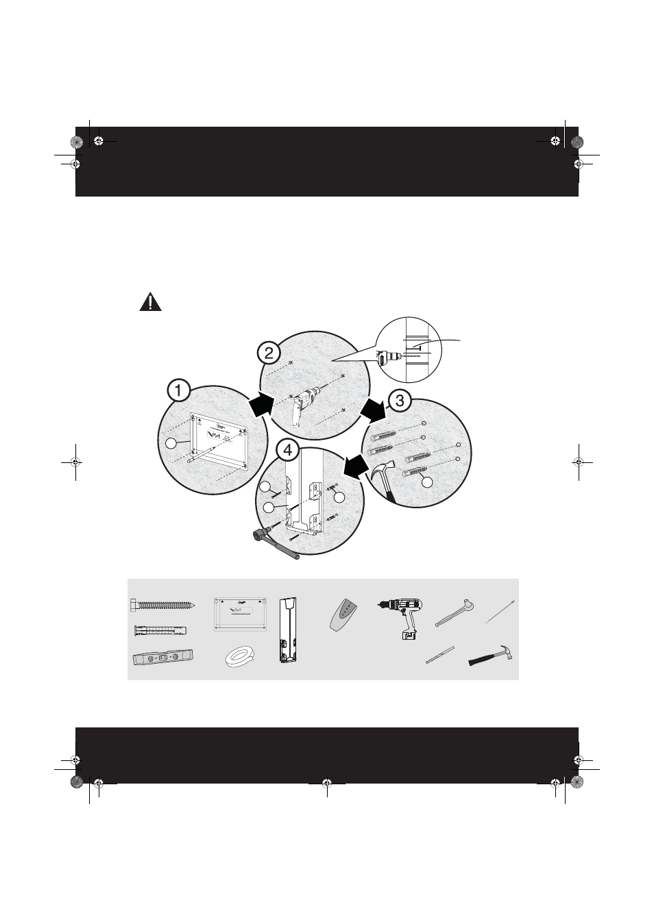
STEP 6 - Option 2: Installing on a solid concrete wall
1
Align the wall plate template (D) at the height you determined in the previous step and make sure that it is
level, then tape it to the wall. Use a pencil to mark the lag bolt hole locations (4). Remove the template.
2
Drill pilot holes to a depth of 3.15 in. (80 mm) using a 3/8 in. (10 mm) diameter masonry drill bit.
3
Insert the concrete wall anchors (W-B) into the pilot holes and use a hammer to make sure that the anchors
are flush with the concrete surface.
4
Align the lift assembly (A) with the anchors, insert the lag bolts (W-A) through the holes in the wall plate,
then tighten the lag bolts only until they are firm against the wall plate.
CAUTION: Avoid potential injuries or property damage!
DO NOT over-tighten the lag bolts (W-A).
You’ll need
W-B
A
W-A
W-B
D
3.18 in.
(80 mm)
Edge-to edge
stud finder
W-A (2)
Pencil
Drill
3/8" masonry drill bit
13 mm socket
wrench
Level
W-B (2)
Hammer
D Template
Tape
A Lift assembly
5.47" (139.0 mm)
9.43" (239.6 mm)
RF-TVML70 Template • Gabarit • Plantilla
Note
Remarque : Pour une construction à ossature de bois, localiser d'abord les montants
en bois, à l'aide d'un détecteur de montants.
Nota: para la instalación en construcciones de armazón de madera, primero debe
localizar las vigas de madera con un localizador de vigas.
Tools Needed
Outils nécessaires
Herramientas requeridas
Top
Dessus
Parte superior
Top
Dessus
Parte superior
RF-TVML70_13-0455_MAN_V3_ENG.fm Page 13 Monday, May 6, 2013 7:45 AM