Electronics LP-24 User Manual
Page 6
6
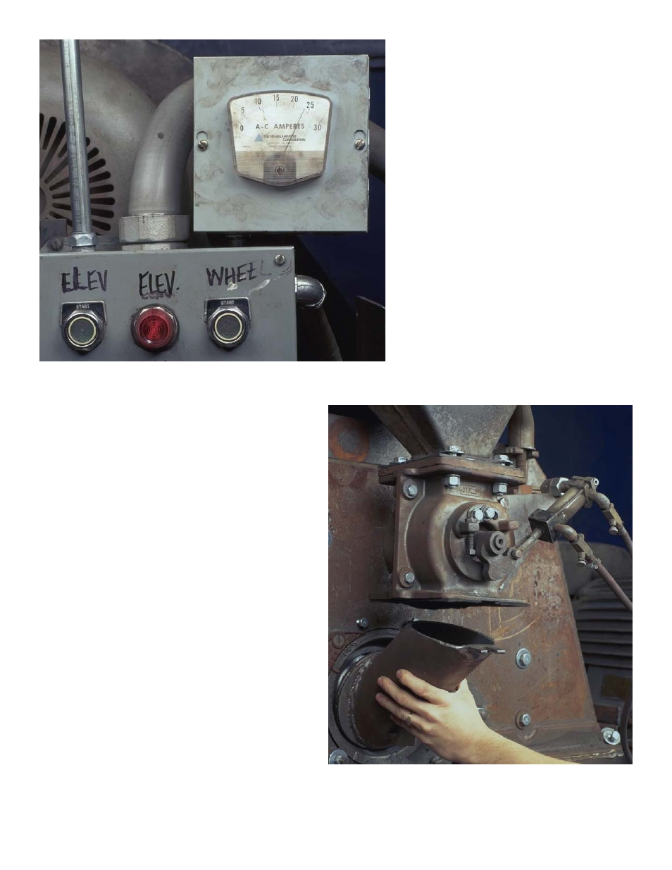
Fig. 4 This figure shows the original
operating amperage level, in this case
approximately 24 amps. Tests indicat-
ed a 4 amp error.
Fig. 5 The first step in removing the
old mechanical valve is to remove the
feed spout going to the wheel inlet.
First, remove the four bolts attaching
the feed spout to the bottom of the me-
chanical valve.
Caution: Be sure the machine is
properly locked out. Follow all safety
precautions and instructions shown on
the machine or in the owner’s manual.
Fig. 4
Fig. 5
See also other documents in the category Electronics Relay:
- Pot-24 (2 pages)
- WM 3000-24 (2 pages)
- WM 3000-24 (10 pages)
- 500-P (10 pages)
- 500-P (2 pages)
- LP2000VAR (2 pages)
- FC (2 pages)
- FC (21 pages)
- LP2000_VAR (2 pages)
- LP2000_VAR (13 pages)
- VLP1000_VAR (2 pages)
- LP-24 (2 pages)
- 576-24 (2 pages)
- AC (2 pages)
- AC (25 pages)
- 578-24 (2 pages)
- 590 (8 pages)
- 590 (2 pages)
- 590-24 (2 pages)
- 590-24 (26 pages)
- 577 (2 pages)
- FC-24 (2 pages)
- FC-24 (12 pages)
- 190-AC (2 pages)
- 100 (2 pages)
- VLP-24 (2 pages)
- 0-120 Vac Variac (1 page)
- AC-24 (16 pages)
- AC-24 (2 pages)
- MC (12 pages)
- MC (2 pages)
- 179-AC (2 pages)
- VLP1000 (2 pages)
- 580-24 (2 pages)
- 178-DC (2 pages)
- 577-24 (2 pages)
- 500-24 (6 pages)
- 500-24 (2 pages)
- 180-AC (2 pages)
- LP2000 (2 pages)
- VLP1000VAR (2 pages)