Electronics LP-24 User Manual
Page 11
11
Fig. 16 Apply control power to the circuit.
Caution: Be sure all wiring has been
properly completed and that no shock
hazard exists. The AC-24 controller is
factory set to display 100.0 Amps full
scale when connected to a 100:5 ratio
current transformer. The display range
can be verified by pressing Coarse Dis-
play Range.
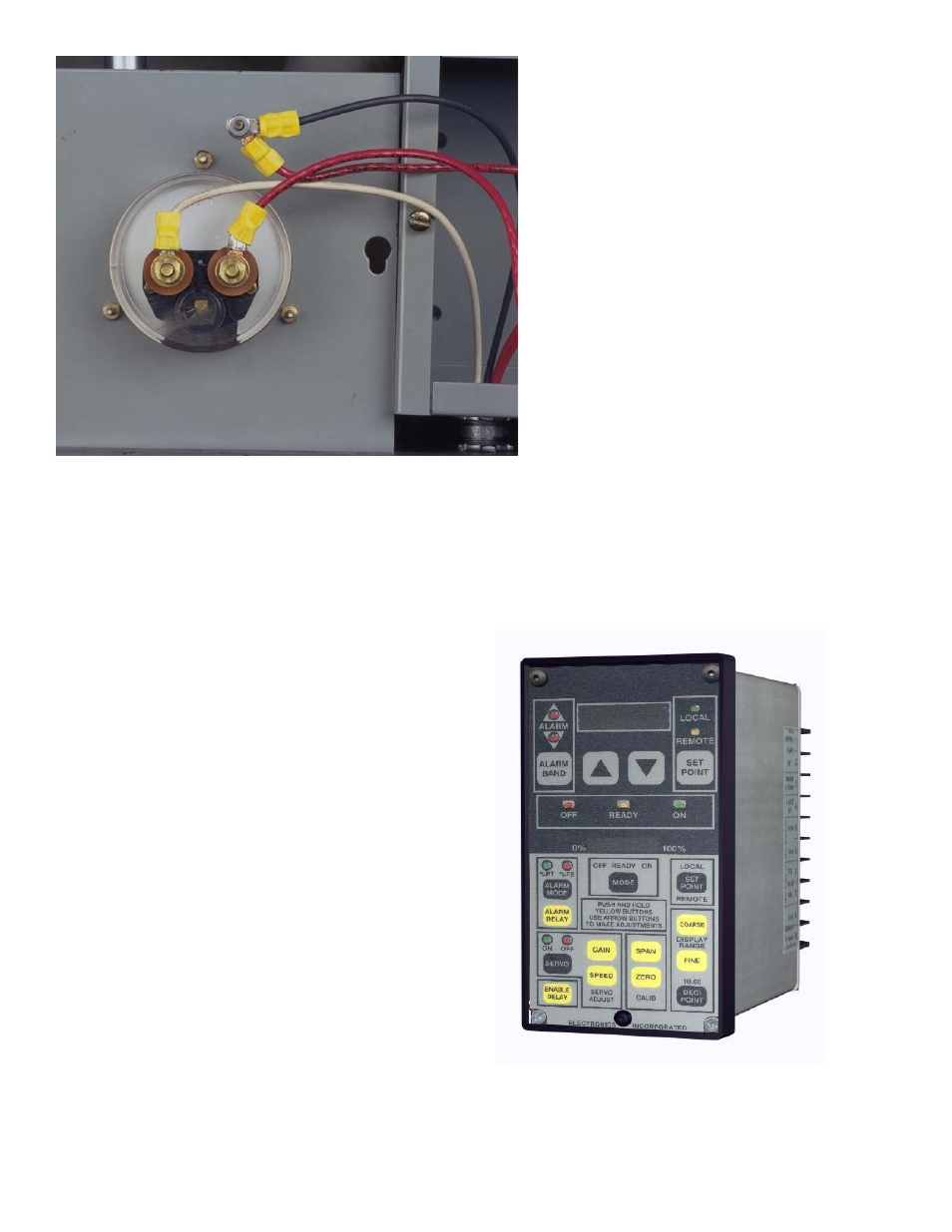
Fig. 15
Fig. 15 Attach the loose current trans-
former wire to one of the AC-24 con-
troller shunt wires and attach the other
AC-24 controller shunt wire to the me-
ter lug. This procedure allows the AC-
24 controller shunt to be in series with
the existing panel meter so that both of
them receive the (transformed) motor
current (0-5 Amps). If the panel meter
is to be eliminated then connect the
two current transformer output wires
directly to the AC-24 controller shunt.
100.0
Fig. 16