Electronics LP-24 User Manual
Page 12
12
30.0
Fig. 17 Since this application uses a 30:5 ratio cur-
rent transformer the AC-24 controller must be ad-
justed to read 30.0 full scale. Press and hold the
Coarse Display Range and Down arrow until 30.0 is
displayed. For finer adjustment use the Fine Dis-
play Range.
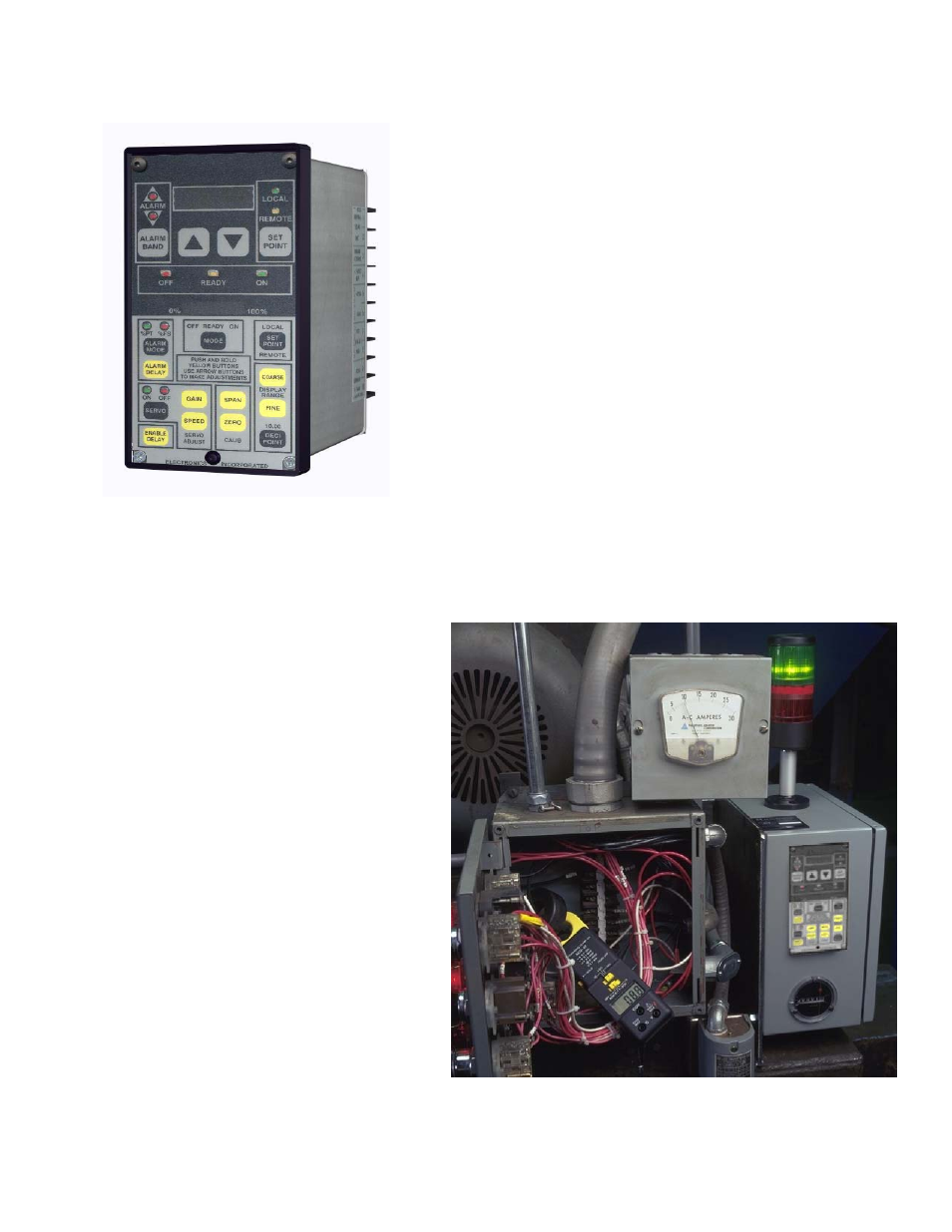
Fig. 18 Start the wheel motor and
place a clamp-on type ammeter on
the motor leads to confirm calibration
of both the panel ammeter and the
AC-24 controller display.
Note: The AC-24 controller zero and
span have been factory set. Minor
adjustments may be needed. Press
the Span button along with up/down
arrows to change value. Release the
Span Button to see new amperage
readings. Make the controller reading
match the clamp-on ammeter read-
ing. Even though there is no shot
flow, ammeter readings will show the
no load or no flow rate values. Note
that the clamp-on ammeter and the
AC-24 Controller digital display show
the no load motor amperage to be
about 8.8 amps, while the panel me-
ter shows over 9 amps.
Fig. 17
Fig. 18