Banks Power Dodge Trucks: (Diesel ’03 - 07 5.9L Cummins) PowerPack & Stinger w_EconoMind '06-07 For use with PowerPDA User Manual
Page 30
30
96813 v.9.0
If not installing optional gauges,
Skip to next section.
1.
choose a suitable location under
the lower edge of the dash for the
mounting of the instrument panel
provided where the driver can
conveniently view it.
Note: Molded pillar mount and
additional gauges are available
through Gale Banks Engineering.
2.
Using the panel as a template,
drill two
3
⁄
16
” diameter holes in the
dash and mount the panel with the
supplied machine screws, nuts and
star washers provided.
3.
Locate the supplied EconoMind
wire loom with the 4-pin connector.
connect the 4-pin connector on
the EconoMind wire loom to the
connection labeled DYNAFAcT
Gauges on the EconoMind wiring
harness. See Figure 17.
4.
Install the DynaFact boost and
pyrometer gauges in the mounting
panel using the clamps and
thumbnuts provided. Plug the BLAcK
wire lead to the male spade terminal
on the BLAcK wire of each gauge
wire harness. Plug the YELLOW wire
into the Yellow wire of the boost
gauge wire harness and the RED wire
into the RED wire of the pyrometer
gauge wire harness. The ORANGE
wire remains unused.
5.
connect the 4-pin connector
of each gauge into the back of its
corresponding gauge.
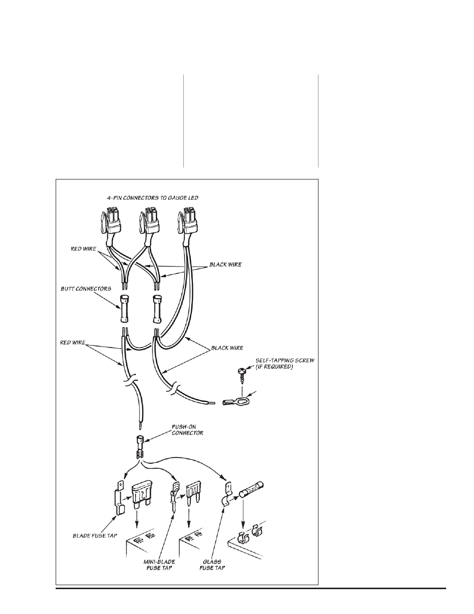
a. crimp the remaining Black and RED
wires from each 4-pin connector
gauge harness to the butt
connectors as shown in Figure 38.
b. Strip one end of the RED wire and
crimp it to the butt connector
containing the RED wires from step
‘a’.
c. Strip one end of the BLAcK wire
and crimp it to the butt connector
containing the BLAcK wires from
step ‘a’.
d. Route the RED wire to the fuse
box. Locate the appropriate fuse
for instrument lighting in the
owner’s manual. cut the RED wire
as required and strip the end.
crimp the push on connector
to the RED wire and connect to
the fuse as shown in Figure 38.
Alternatively, locate power wire to
dimmer switch and install T-tap.
cut the RED wire as required and
strip the end. crimp the push on
T-tap connector to the RED wire
and connect to T-tap on dimmer
power wire.
e. Locate a metal surface that will
serve as an acceptable chassis
ground. cut the BLAcK wire to a
sufficient length that will allow it to
reach the chassis ground and strip
the end. crimp the ring terminal
to the BLAcK wire as shown in
Figure 38.
f. Drill a
1
⁄
8
” hole, if required, to
attach the ring terminal to the
chassis ground. Caution: If
drilling, check the backside
to make sure there are no
components that may be
damaged by drilling.
g. Use the supplied self-tapping
screw to secure the ring terminal
to the chassis ground.
-END, SEcTION 8-
Section 8
oPTIoNAL GAuGE CLuSTER INSTALLATIoN
Figure 38