Banks Power Dodge Trucks: (Diesel ’03 - 07 5.9L Cummins) PowerPack & Stinger w_EconoMind '06-07 For use with PowerPDA User Manual
Page 12
12
96813 v.9.0
Note: For installation of the
Banks Stinger System proceed to
Section 3.
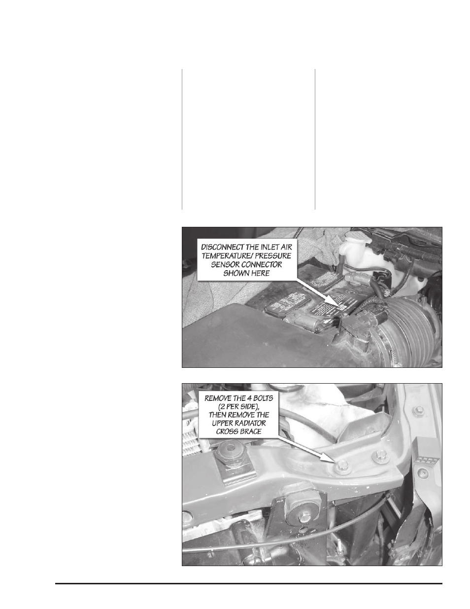
1.
Disconnect the Inlet Air
Temperature/ Pressure Sensor
connector located on the air box
cover. The connector is shown in
Figure 7.
2.
Remove the nut that fastens the
air filter housing to the radiator cross
brace.
3.
Loosen the hose clamp that
secures the air inlet duct to the
turbocharger inlet. Disconnect the
inlet duct from the turbocharger.
4.
Remove the air box and inlet
duct as an assembly. The air box is
held in place with re-usable push-
in fasteners and can be pulled out
vertically.
5.
Remove the passenger side
boost tube. The boost tubes are the
charge air ducting that route air from
the turbocharger to the charge Air
cooler (cAc) and from the cAc to
the intake manifold.
6.
cover the turbocharger inlet and
outlet with a clean rag to prevent
foreign debris from entering these
locations.
7.
Remove the bolt that holds the
engine oil dipstick to the intake. Save
the bolt for re-use.
8.
Remove the electric heater wire
harness from the stock intake by
pulling the plastic pin out. Remove
the wire harness brackets that are
mounted on the intake by removing
the nut and washer.
9.
Unbolt and remove the 4 bolts
at the base of the stock intake.
Remove the stock intake from the
vehicle. cover the intake manifold
opening with a clean rag to prevent
any foreign debris from entering the
engine through the heater block.
10.
Remove the driver side boost
tube.
11.
Remove the two upper radiator
attachment bolts.
13.
Remove the two upper cAc
attachment bolts.
14.
Remove the 4 bolts (2 per
side) that retain the upper radiator
cross brace, then remove the upper
radiator cross brace. The brace is
shown in Figure 8.
15.
Remove the 4 hex head bolts
that attach the A/c condenser
mounting brackets to the cAc.
16.
Swing the A/c condenser
upward as shown in Figure 9, then
out away from the vehicle as shown
in Figure 10.
Caution: Minimize the amount of
stress to the A/C condenser fluid
lines to prevent damage.
An assistant could be helpful to hold
the A/c condenser while the stock
cAc is being removed and the Banks
Techni-cooler is being installed.
17.
Remove the stock cAc from the
vehicle.
18.
Remove the lower saddle mount
rubber bushings from the stock cAc
and install them on the Banks Techni-
cooler.
19.
Remove the upper rubber
isolators from the stock cAc and
install them on the Banks Techni-
cooler.
20.
Install the Banks Techni-cooler
in the vehicle.
21.
Remove all factory brackets
from the condenser, retain the torx
head bolts for reassembly.
22.
Place the A/c condenser back in
front of the Techni-cooler.
Figure 7. Location of the Inlet Air Temp/ Pressure Sensor
Figure 8. Upper radiator cross brace