Banks Power Dodge Trucks: (Diesel ’03 - 07 5.9L Cummins) PowerPack & Stinger w_EconoMind '06-07 For use with PowerPDA User Manual
Page 13
96813 v.9.0
13
23.
Install the R.U. and L.U.
brackets onto the condenser and
assemble the condenser to the banks
intercooler using the
5
⁄
16
” button
head bolts and washers provided.
Install the R.L and L.L brackets
onto the condenser such that the
intercooler boss and condenser holes
align. (see Figure 11).
Note: The Banks condenser brackets
are stamped such that “R.U.” means
Right (Passenger Side) Upper and
that the “R.U.” is visible when the
condenser is installed.
24.
Tighten the
5
⁄
16
” bolts at each
of the A/c mounting brackets and
torque to 19 ft-lbs.
25.
Tighten the torx head bolts on
both of the lower and the upper A/c
mounting brackets.
26.
Install the upper radiator cross
brace. Leave the bolts loose to aid in
the alignment of the cross brace with
the radiator and Techni-cooler.
27.
Loosely install the upper cAc
mounting bolts.
28.
Loosely install the upper radiator
mounting bolts.
29.
Tighten the radiator cross brace
bolts and torque to 21 ft-lbs
30.
Tighten the upper cAc mounting
bolts and torque to 8 ft-lbs (96 in-lbs).
31.
Tighten the upper radiator
mounting bolts and torque to 8 ft-lbs
(96 in-lbs).
32.
Install the passenger side boost
tube. The passenger side uses a 2.75
inch diameter straight hose at the
turbocharger connection, and a 3.5
inch diameter hump hose at the cAc
connection. The orientation of the
hose clamps should be as shown in
Figure 12 to avoid clearance issues.
Do not install the straight hose onto
the turbocharger, and keep the hose
clamps at the cAc connection loose
until the thermocouple is installed in
Section 3. cover the opening of the
boost tube to prevent foreign objects
from entering the boost tube during
the installation.
NOTE: Before slipping any boost
tubes and the corresponding
hoses, into position, ensure that all
connection ends are clean and free
of any oil residue and contaminates.
Clean compressor outlet and all
connection points with a non-oil
based solvent such as Acetone,
Mineral Spirits, Denatured Alcohol or
Lacquer Thinner. Read and follow the
manufactures operation instruction
for non-oil based solvent cleaner.
33.
Install the driver side boost
tube. The driver side tube uses a
3.5 inch diameter straight hose at
the intake manifold and a 3.5 inch
diameter hump hose at the cAc.
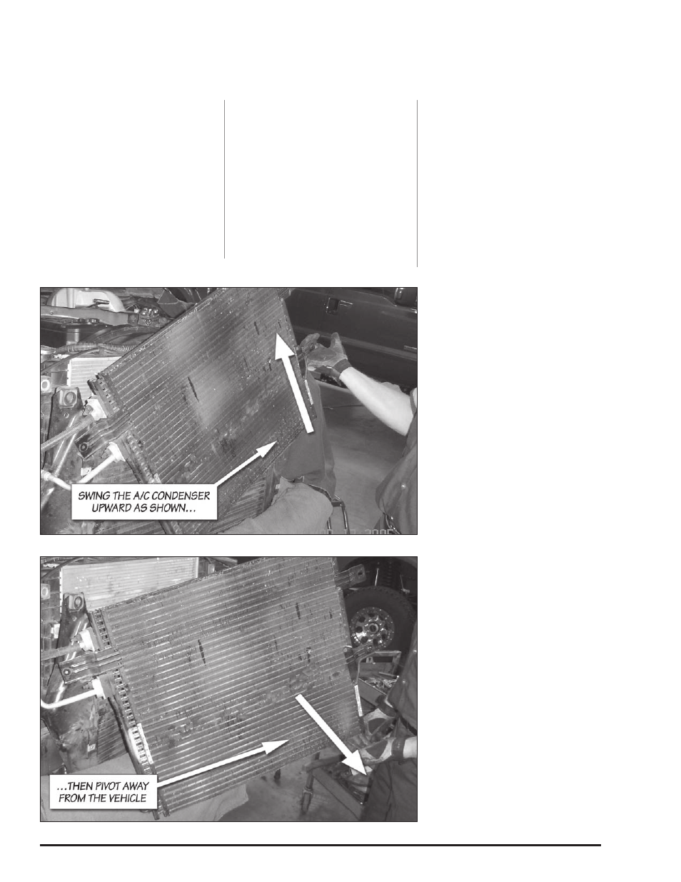
Figure 9. A/C condenser removal procedure
Figure 10. A/C condenser removal procedure