Banks Power Dodge Trucks: (Diesel ’03 - 07 5.9L Cummins) PowerPack & Stinger w_EconoMind '06-07 For use with PowerPDA User Manual
Page 14
14
96813 v.9.0
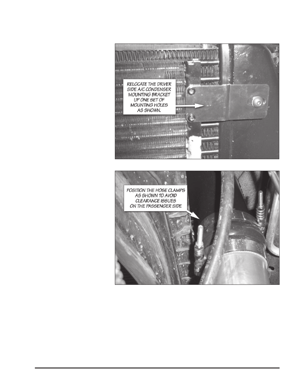
The orientation of the hose clamps
should be as shown in Figure 13
to avoid clearance issues. Keep the
hose clamps loose until the High Ram
is installed. cover the opening of the
boost tube to prevent foreign objects
from entering the boost tube during
the installation.
34.
Remove the three wires on the
electric heater block at the intake
manifold, then remove the heater
block. Save the fasteners for re-use.
Caution: Cover the opening in the
intake manifold with a clean rag
to prevent foreign objects from
entering the engine.
35.
completely remove the stock
gaskets from both sides of the heater
block and intake manifold. Take care
not to scratch or gouge any of these
surfaces when removing the gasket
material.
36.
Remove the rag that was used
to cover the intake. Reinstall the
electric heater block onto the intake
manifold with one of the supplied
gaskets. Reattach the three electrical
connections to the heater element.
37.
Caution: The High Ram studs
have different threads on each
end. Make sure the M8 ends go
into the engine intake manifold.
The shorter studs are placed inboard
closest to the valve cover. Apply the
supplied thread locking compound
to the M8 threaded end of the studs.
Hand tighten the studs to the intake
manifold.
38.
Using the two
5
⁄
16
”-24 nuts
supplied, tighten the studs into
the intake by threading both nuts
onto the stud, then tighten the nuts
against each other with two
1
⁄
2
” open
end wrenches. Tighten and torque
the stud to 2 ft-lbs by turning the top
nut. Remove the nuts from the stud
by using two open-end wrenches to
loosen the nuts in relation to each
other. Repeat the process for each
stud. The process
is shown in Figure 14.
Figure 12. Orientation of the passenger side hose clamps to avoid clearance issues.
Figure 11. Relocation of the upper driver side A/C condenser mounting bracket