Banks Power Dodge Trucks: (Diesel ’03 - 07 5.9L Cummins) PowerPack & Stinger w_EconoMind '06-07 For use with PowerPDA User Manual
Page 29
96813 v.9.0
29
NOTE: Do not tape over the markings
on the template.
22.
Skip to Step 24 to continue.
23.
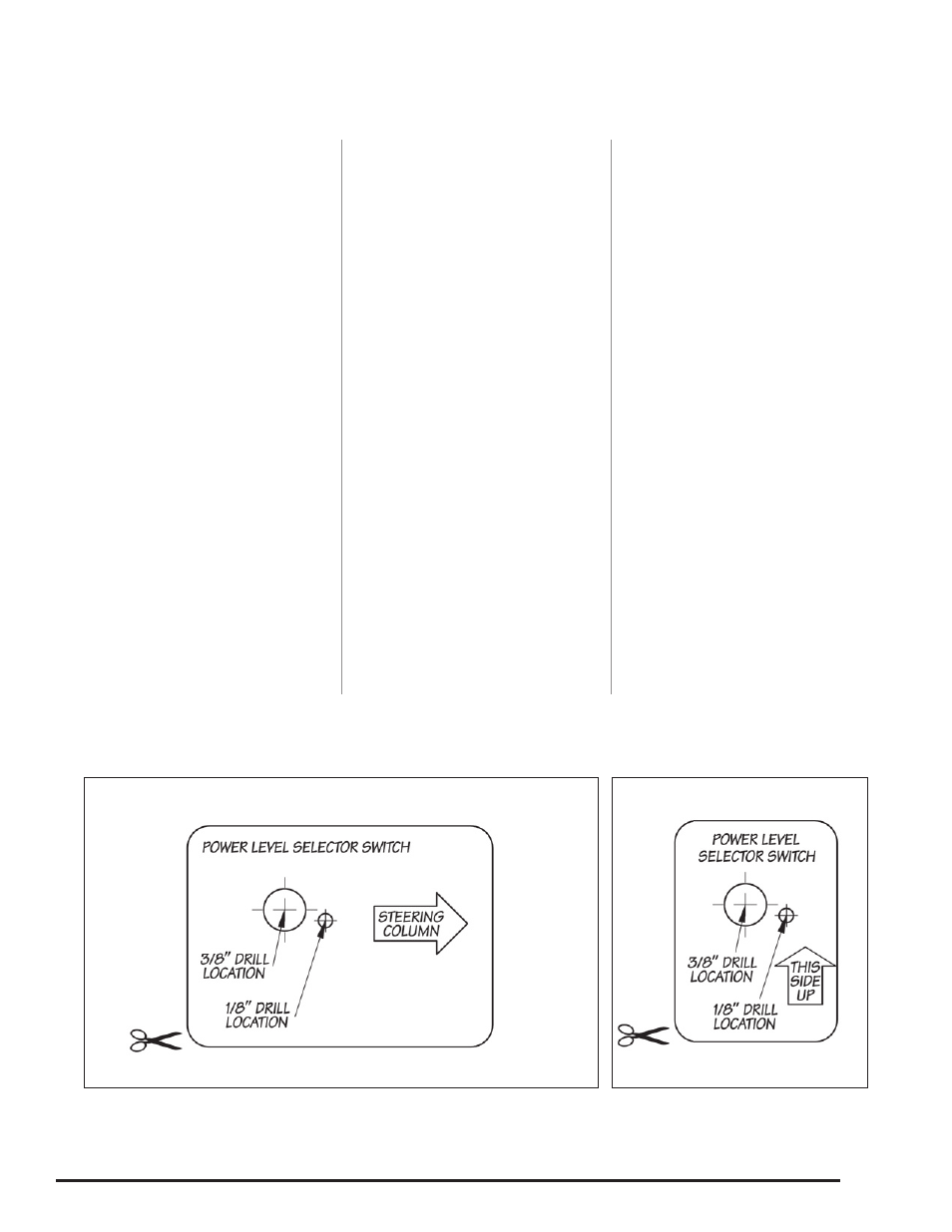
cut out the supplied template
(see Figure 37a) and align the
template onto the front of the cluster
bezel by placing its left edge against
the cluster rib, and its bottom edge
against the cluster bottom edge. Use
masking tape to securely hold down
the template.
NOTE: Do not tape over the markings
on the template.
24.
Using a
3
⁄
8
” Uni-drill, center the
bit onto the
3
⁄
8
” drill location on the
template and slowly drill through the
panel. Using a
1
⁄
8
” drill bit, center and
drill through the
1
⁄
8
” location on the
template. Remove and discard the
template and any plastic shavings.
NOTE: It is important that the hole is
drilled at the recommended location.
The switch may not clear the
instrument panel structure if the hole
is shifted to another location.
25.
Align the Banks power level
selector label onto the previously
drilled hole. Make sure the entire
mounting surface is clean and free of
dirt and oil before mounting the label.
clean and dry as required using a
cloth dampened with rubbing alcohol
or similar cleaning solution.
CAuTIoN: Do not spray fluid
directly onto any electrical
equipment, or equipment damage
may result.
Mount the Banks power level selector
switch label onto the drilled panel
by peeling the protective backing
off the adhesive tape on the back
of the switch label. Hold the label
against the panel for approximately
20 seconds while applying pressure
to allow the adhesive to properly
adhere to the surface.
26.
Remove the nut and internal
tooth washer from the power level
selector switch. Rotate the shaft
counter clockwise until the shaft
stops. Verify that the locating washer
tab is inserted into the #6 position on
the switch (see Figure 36).
NOTE: If the washer is in any position
other than the #6, your EconoMind
Diesel Tuner will not select power
levels correctly.
27.
After confirming the locating
washer is in the #6 location, install
the switch through the
3
⁄
8
” hole
on the backside of the bezel. The
alignment pin should rest in the
1
⁄
8”
hole and with the switch fully rotated
counter clockwise; the shaft’s flat
side should be facing the steering
column. Secure switch with internal
tooth washer and nut. Snug the nut.
Be careful not to over torque the nut
and damage the plastic threads.
28.
Install the knob onto the shaft
facing the #1 Level on the power
level selector label. On the knob,
snug the two (2) set screws with the
supplied 0.050” hex key wrench.
29.
Reinstall the removed panels.
Make sure to reconnect all electrical
connecters disconnected previously.
30.
Route the power level selector
switch wires down to the steering
column.
31.
Route the power level selector
switch’s cable to the wire harness
that was routed into the passenger
compartment from the EconoMind
module, and plug the 2-pin connector
into the corresponding connector on
the EconoMind wiring harness.
32.
Re-install the electric connector
bracket that was removed in Step
4 of Section 5 below the steering
column in the front of the firewall
with the original two (2) bolts.
-END, SEcTION 7-
Figure 37a
Figure 37b