Banks Power Dodge Trucks: (Diesel ’03 - 07 5.9L Cummins) PowerPack & Stinger w_EconoMind '06-07 For use with PowerPDA User Manual
Page 17
96813 v.9.0
17
1.
The thermocouple monitors the
temperature of the exhaust gases
entering the turbocharger at the
turbine housing. Installation requires
that the exhaust manifold be drilled
near the outlet of the manifold
adjacent to the turbine housing.
For this reason it is essential that
the turbocharger be removed from
the engine in order to clean out any
metal chips from drilling that could
cause turbine blade damage.
NOTE: The Cummins ISB engine uses
a divided exhaust manifold. The
thermocouple may be installed to
sample exhaust temperature in either
exhaust passage. We recommend the
rear passage (toward the firewall).
2.
If not already done, remove the
factory air intake system as described
in Section 2 Steps 1-4.
3.
Loosen the upper hose clamp on
the turbocharger oil drain-tube hose
that is located between the two
sections of the oil drain tube.
4.
Disconnect the oil supply hose
at the turbocharger. Disconnect the
compressor outlet hose that goes to
the intercooler.
5.
Disconnect the turbine outlet pipe
by loosening the V-band. Save V-band
for re-installation.
6.
Remove the turbocharger
mounting nuts/bolts and the
turbocharger from the exhaust
manifold. clean and inspect the
exhaust flange mounting surfaces on
the exhaust manifold. Make sure the
surface is clean and dry.
CAuTIoN: Anytime the
turbocharger is removed from
the engine, take care that no
foreign objects enter any of the
turbocharger connections on
the engine or the turbocharger.
Foreign objects entering air,
exhaust, or oil connections may
cause major damage to the engine
and/or turbocharger and is not
covered under any warranty.
Cover the open end of the
intercooler pipe with a clean rag,
as this pipe is very susceptible to
foreign object entry.
7.
Stuff clean shop towels into the
compressor outlet and inlet hoses
to prevent contamination from
entering the pipes. cover the turbo oil
drainpipe to avoid contamination.
8.
Stuff a small clean shop towel
or rag 4 to 5 inches into the rear
exhaust manifold passage through
the turbocharger mounting flange.
This is to prevent chips from entering
the manifold while drilling and
tapping.
9.
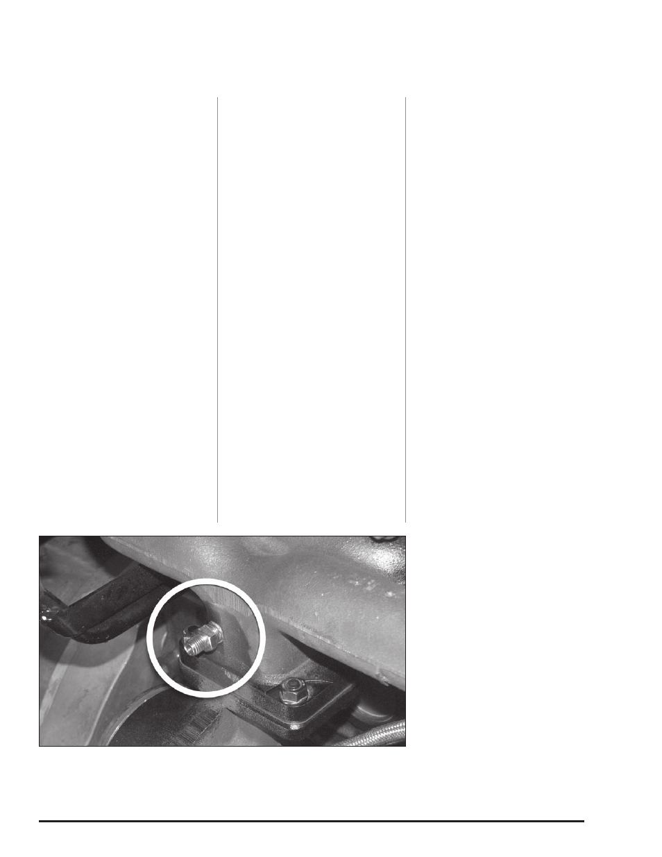
Use a
7
⁄
16
” drill, keeping the drill
perpendicular to the manifold surface
and drill through the exhaust manifold
into the rear passage as shown in
Figure 16.
10.
Tap the drilled hole with a
1
⁄
4
”
NPT pipe tap. check the thread
depth as you tap by periodically
removing the tap and screwing the
pipe coupling into the tapped hole.
The coupling should thread in 3 to 3
1
⁄
2
turns hand tight. Do not install the
probe in place at this time.
11.
Remove all loose chips from the
exhaust manifold. A shop vacuum or
small brush will help. Now remove
the rag using a welding rod or coat
hanger bent into a hook.
Caution! Make sure rags are
removed from exhaust manifold
prior to reinstalling turbocharger!
12.
Install the pipe coupling into
the manifold using anti-seize on the
threads. Install the thermocouple and
tighten.
CAuTIoN: Remove all the rags that
are inside the compressor outlet
and inlet hoses and the exhaust
manifold before re-installing the
turbocharger.
13.
Install the new turbine inlet
gasket provided and apply a dab
of anti-seize compound to the
four turbo mounting studs. Install
the turbocharger on the exhaust
manifold. As the turbocharger is
reinstalled, slip the oil drain tube
into the drain hose. Tighten the
turbocharger mounting nuts to 24 ft-
lbs. Tighten the oil drain hose clamp.
14.
Reconnect and tighten the turbo
oil supply hose.
15.
Reconnect the turbine outlet
pipe to the turbocharger and secure it
with the V-band.
16.
Re-install the air box and inlet
tube assembly. Secure the air box
at the radiator cross brace with
the factory nut that was previously
removed. Re-connect the Air Inlet
Temperature/ Pressure sensor at the
air box cover. Re-connect the air inlet
duct to the turbocharger inlet. Tighten
the hose clamp at the turbocharger
inlet to 8 ft-lbs (96 in-lbs).
17.
Re-connect the compressor
outlet hose that goes to the
intercooler and tighten all hose
clamps to 5 ft-lbs.
-END, SEcTION 3-
Section 3
THERMoCouPLE INSTALLATIoN
Figure 16