Rough Country 234N2 User Manual
Page 6
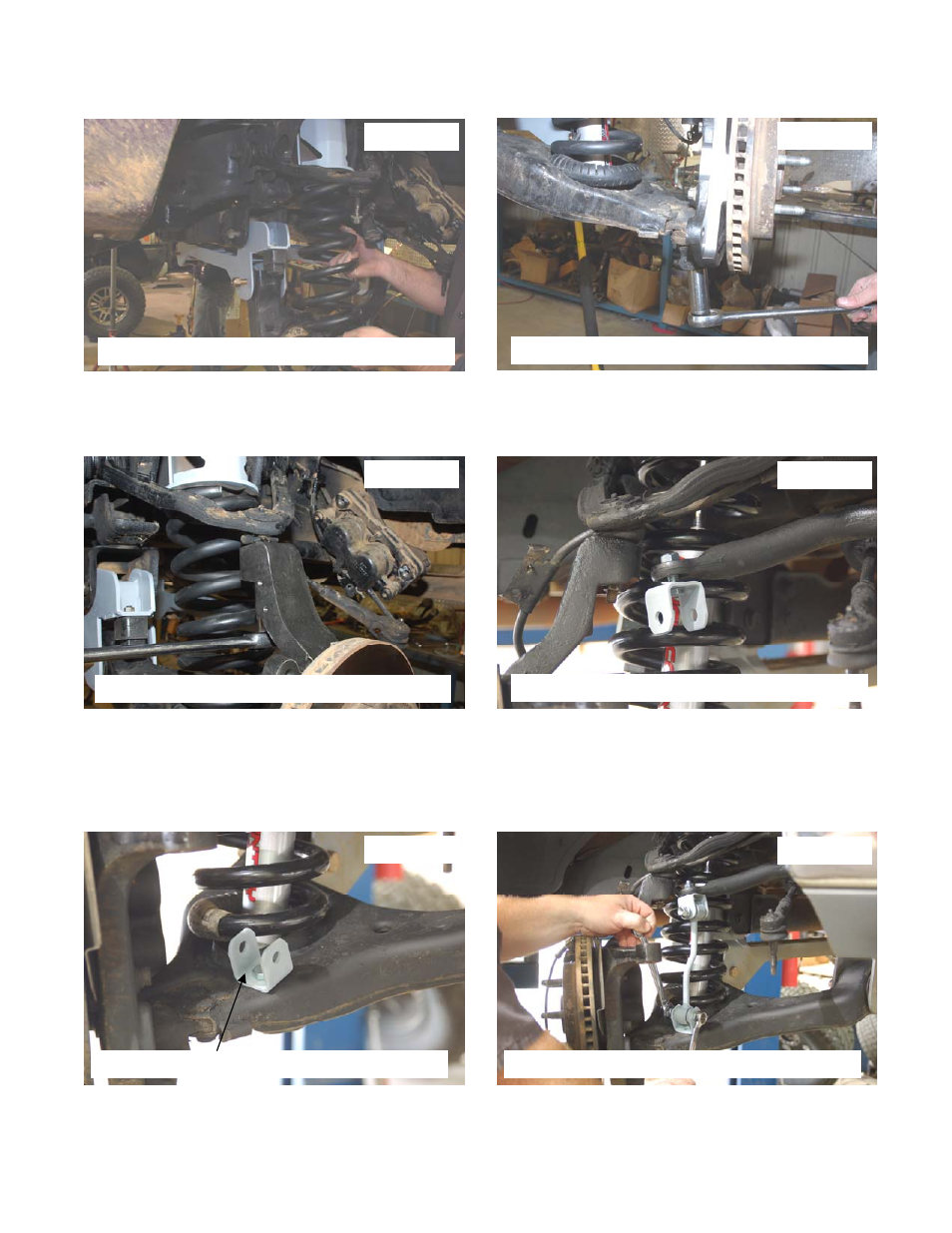
27. Position the coil on the upper coil spacer and swing up the arm making sure the coil spring seats in the lower control
arm. See Photo 25. Support using a floor jack.
28. Install the knuckle on the lower ball joint with the stock hardware and tighten using a 24mm wrench. See Photo 26.
29. Jack up the lower arm, compressing the coil spring and attach the upper control arm to the knuckle with the stock
hardware. Tighten using a 18mm socket. See Photo 27.
30. Install the bracket on the sway bar with the supplied 12mm x 35mm bolt and flange lock nut. The bolt will install from
the bottom up. See Photo 28. Do not tighten at this time.
31. Install the bracket on the lower control arm as shown in Photo 29 and secure with the supplied 12mm x 35mm bolt
and flange lock nut.
32. Install the link and position upper and lower mounts. After they have been moved into position, remove the link and
tighten the upper and lower mounts using a 18mm socket and wrench.
33. Re-install the link as shown in Photo 30 and secure with the 12mm x 65mm bolts and flange lock nuts. Tighten us-
ing a 18mm socket and wrench.
PHOTO 25
PHOTO 26
PHOTO 27
PHOTO 28
PHOTO 29
PHOTO 30
INSTALL THE COILS
INSTALL KNUCKLE AND TIGHTEN
TIGHTEN THE UPPER BALL JOINT
INSTALL THE SWAY BAR BRACKETS
INSTALL THE SWAY BAR BRACKETS
INSTALL THE SWAY BAR LINKS IN BRACKET