Rough Country 7503 User Manual
Page 3
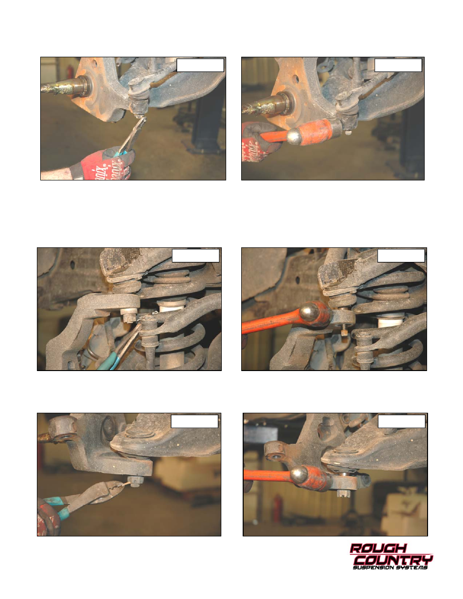
7. Using pliers remove the cotter pin from the tie rod. See Photo 7.
8. Using a 21mm socket remove the castle nut. Using a hammer hit the spindle only as shown in Photo 8 until the tie
rod pops out. Do not strike the tie rod itself or the threaded shaft. Retain the hardware for reuse.
9. If your vehicle has an anti-lock brake system, remove the sensor from the spindle. This will be reinstalled on the
new spindle.
10. Support the lower control arm with a jack. Raise the lower control arm 1”. This should be enough to relieve the ten-
sion on the shock.
11. Using pliers remove the cotter pin from the upper ball joint. See Photo 9.
12. Using the 21 MM wrench loosen castle nut. Using a hammer hit the spindle as shown in Photo 10 until the upper
ball joint pops out. Do not strike the ball joint itself or the threaded shaft.
13. Using pliers remove the cotter pin from the lower ball joint. See Photo 11.
14. Using the 24mm socket loosen the castle nut. Using the hammer hit the spindle as shown in Photo 12 until the ball
joint breaks free. Do not strike the ball joint itself or the threaded shaft. Remove the upper and lower castle nut and
place spindle aside. Retain hardware for reuse.
PHOTO 7
PHOTO 8
PHOTO 9
PHOTO 10
PHOTO 11
PHOTO 12