B&W Trailer Hitches Turnoverball Model 1303 (Dodge) User Manual
Page 3
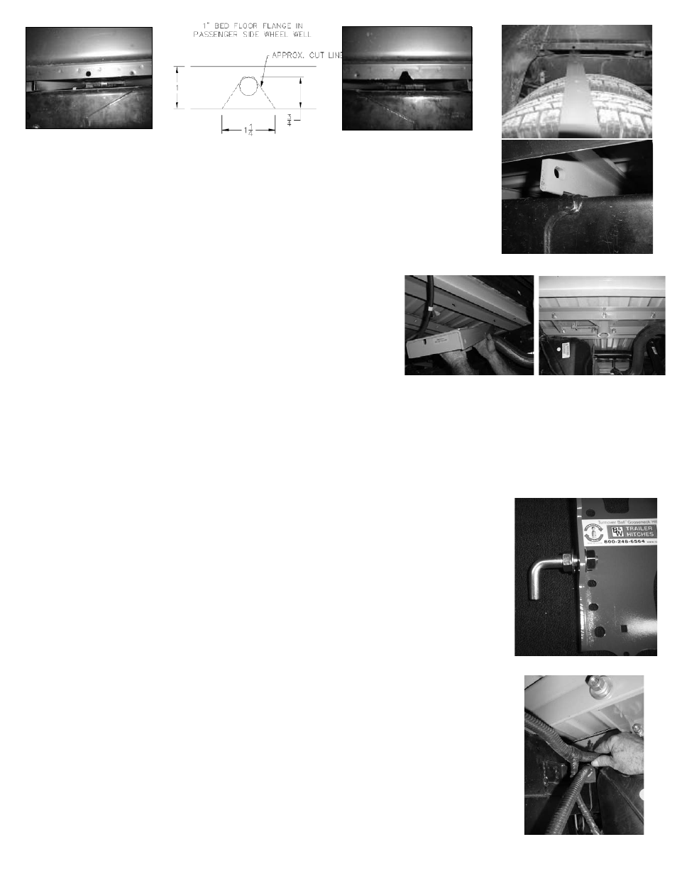
Install the 1”x 2” bar making sure that the outer two holes will be tow
ard the top of the
bar when it is turned up vertical. Slide forward to bed crossmember. Next using the notch for
clearance install the angle iron with the angle oriented so that the leg with slotted holes will
be toward the front of the truck and the horizontal leg will be at the top against the truck bed
f oor. Hold the angle in an inverted V position , and push the angle across the frame. With the
angle spanning the frame, move it reward toward the bed crossmember.
STEP 3
Install the center section. With the latch pin on the driv
er’s
side and the socket offset to the front of the truck, raise the center
section up over the differential guiding the ring into the 4 inch hole
in the truck bed f oor. Pull the angle iron forward against the center
section and install the center bolt, leaving the nut just barely started
on the bolt. Install the 1 ½” bolts, lock w ashers, and f at washers
from inside the center section threading the bolts into the holes in
the front bar. Next install the 1 1/2” bolts from inside the center
section to the rear angle iron. F asten with f at washer, lock washer
and nut.
Do not tighten at this time.
STEP 4
Fig. 2
The sideplates will have to be installed with the center section bolts still loose, so
that the sideplates can be positioned between the bar and angle. On the long f ange of
the front sideplate fasten a L-bolt with two 5/8” serrated f ange nuts in the lower round
hole. The f ange on the nuts must face each other sandwiching the sideplate f ange
between them. (see f g.2 )
On some 2005 and newer model trucks there will not be a 5/8” diameter hole on
the drivers side of the fr ame to accommodate the L -bolt. For these models there are
two 8 mm self threading bolts supplied that will go though the two slotted holes in the
lower part of the side plate. They should align with the holes in the fr ame. Start the
self threading bolts though the side plate and into the fr
ame. Do not fully tighten at this
time. The holes in the fr ame may be used for the emergency br ake cable bracket. In
this case remove the bracket and place the 5/16”x 1’ carriage bolt in the square hole
at the lower part of the side plate. Place the carriage bolt though the side plate with
the threads facing out. Place the brake cable bracket over the carriage bolt and secure
with the 5/16” f ange nut.
If the hole for the L -bolt is present on the driv er’s side then position the front
sideplate between the bar and angle. Place a bolt with lock and
f at washers though the
sideplate and thread into the outer hole of the bar, at the same time f t the L- bolt into
the hole in the frame just in front of the sideplate while pushing the sideplate against
the frame (the L-bolts my have to be tapped into the hole). Next install the front (gold
colored) U-bolt from inside the frame through the holes in the sideplate abo
ve and below
the frame. To install the front (gold colored) U-bolt on the driv er’s side it is necessary
to remove a wiring harness frame clip (see f g. 3), place the U-bolt against the fr ame
staying under the wiring harness, and brake line. While making certain that nothing is
between the frame and U-bolt, raise the U-bolt until the top leg is level with the top of
the frame rail. Then turn the legs outward to the front sideplate f tting the legs into the
holes in the sideplate above and below the frame. Replace the wiring harness frame clip
and fasten the U-bolt, using a lock washer and nut on each end of the U-bolt.
Fig. 3