Model 1105r, Turnover ball, Gooseneck hitch installation instructions – B&W Trailer Hitches Turnoverball Model 1105 (Ford) User Manual
Page 2: Call or email us for installation support
Model 1105R
Copyright 2005
B&W Custom Truck Beds, Inc.
ALL RIGHTS RESERVED
UNITED STATES PATENT No. 5016898
1105R-022406
www.turnoverball.com
Call or Email us for Installation Support
800.248.6564
Turnover Ball
TM
Gooseneck Hitch Installation Instructions
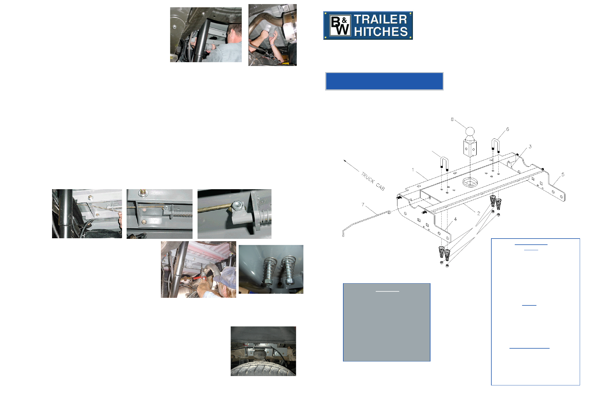
Parts List
1 – Front Crossmember
2 – Rear Crossmember
3 – Center Section
4 – Driver’s Side Sideplate
5 – Passenger’s Side Sideplate
6 – Safety Chain U-Bolts
7 – Latch Pin Handle
8 – Turnover Ball
9 - Springs
10 - 1/2” Lock nuts
STEP 7
Raise the center section (3) into position between the
crossmembers from beneath the truck, with the latch pin release
handle on the driver’s side. A lifting device, as described on Page 1
will help. The round hitch receiver that protrudes from the top of the
center section must fit through the hole in the truck bed floor. Fasten
the center section to the crossmembers using the six 1/2” x 1 1/2”
bolts. Fit these bolts through the slots in the crossmembers using a
flat washer against the bolt head and a lock washer under the nut
on each. Do not fully tighten at this time.
Square the assembled center section and crossmembers across the frame. Install the side plates on the outside of
the frame rails by hanging the top two holes in the side plates over the studs extending from the ends of the crossmembers.
Fasten the sideplates to the crossmembers using a 1/2” flange nut on each stud. On 2004 and older trucks place a 5/16”
carriage bolt through the small lower square hole in the driver’s side sideplate, for attaching the emergency brake cable
bracket. Place a pipe spacer between the sideplate and frame and insert a 3/4" X 2 1/2" carriage bolt from outside of the
frame rail in the front mounting hole. Note: the use of carriage bolts will allow air bags to be installed on the outside of the
frame if desired. Insert a 3/4" X 2 1/2" bolt through the 3"X5" frame spacer plate, and install it from the outside of the truck
frame rail through the rear sideplate hole and the frame. The spacer should stand vertically inside the frame and hold the bolt
in the proper location even though the shape of the frame hole varies. The spacer will align the side bracket plate with the
hole. Once both sideplates are installed, then tighten all four 3/4" bolts on the sideplates to 90-ft. lbs. torque. Tighten all 1/2"
bolts on sideplates, angles and center section to 80-ft. lbs. torque. (Use caution not to damage the brake line or fuel line.).
STEP 8
STEP 9
WHEN INSTALLING AFTERMARKET AIR RIDE SUSPENSION A LONGER HANDLE MAY BE NECESSARY. THEY ARE
AVAILABLE FROM YOUR TURNOVER BALL DEALER OR FROM B&W. (PART NUMBER GNXA1800)
Install the latch pin release handle (7) by inserting the handgrip end of the handle rod from inside the center section
through the hole in the endplate. Align the handle loop and the hole in the tab on the end of the latch pin assembly, putting the
handle loop on the correct side of the tab and bolt together using the 3/8” x 3/4” bolt and lock nut. When properly attached,
the center of the handle should be in line with the center of the pin assembly, and the bolt head should be on the loop side,
and the nut on the tab side. Tighten the bolt.
STEP 10
To install the safety chain brackets (6) it is necessary to
drill four 1/2” holes through the truck bed floor. Drill the holes
from beneath the truck, through the four holes located farthest
from the round receiver tube in the center section. This will
locate the safety U-Bolts (6) in the lowest point of the floor
corrugation. Drop a U-bolt through each pair of holes from the
top side of the truck bed floor. Place a spring and lock nut on
each of the four legs. Tighten the lock nuts until flush with the
bottom of the U-bolts.
STEP 11
Retract the latch pin by pulling the handle all the way out until it stops and then rotate it clockwise. Place the Turnover
Ball (8) in the hitch receiver. Engage the latch pin by rotating the handle counterclockwise. Be certain the latch pin passes
through the holes in the Turnover Ball and fully engages through the hitch receiver. Remove
and grease the square base of the Turnover Ball.
GENERAL INFORMATION
If installing after-market air ride suspension components do so according to the manufac-
turers specifications by drilling the air-ride system bracket holes through the B&W sideplates.
Note: B&W sideplates will add a 1/4” thickness to the frame rail dimension, so make
certain that the air-ride bracket bolts are the correct length.
2 ea. - 3/4” x 2 1/2” Carriage bolts
6 ea. - 1/2" X 1 1/2" bolts
2 ea. - 3/4" X 2 1/2" bolts
6 ea. - 1/2" flat washers
2 ea. - 3/4" flat washers
6 ea. - 1/2" lock washers
4 ea. - 3/4" lock washers
6 ea. - 1/2" nuts
4 ea. - 3/4" nuts
Bag 2
2 ea. - 3” x 5” spacers
4 ea. - 1/2” Flange nuts
2 ea. - pipe spacers
3 ea. - 5/16 x 1” Carriage bolts
3 ea. - 5/16 flange nuts
1 ea. - Fuel line bracket
1 ea. - Exhaust bracket extension
Safety Chain Kit
2 ea. - 1/2" U-bolts
4 ea. - 1/2" lock nuts
4 ea. - springs
1 ea. - 3/8”x3/4” Bolt
1 ea. - 3/8” Lock nut
B&W Trailer Hitches
1216 HWY 224 / PO Box 186
Humboldt, KS 66748
P:620.473.3664
F:620.473.3766
Hardware Kit
Bag 1
9
10
6
Ford Super Duty (1999 -2006)
3/4 & 1 Ton, Short & Long Bed
Will Accommodate Most After Market Air Bag Systems