Before installing, Installation instructions – B&W Trailer Hitches Turnoverball Model 1306 (Dodge) User Manual
Page 2
The emergency brake cable bracket may need to be removed
to install the side plate on the driver’s side. In this case the frame
may have a similar set of holes forward of the bracket that it can
be relocated. If no holes are available for relocation of the brake
cable bracket a 5/16” X 1” carriage bolt is provided. Place in the
square hole at the lower part of the side plate. Insert the carriage
bolt through the side plate with the threads facing out. Place the
brake cable bracket over the carriage bolt and secure with a 5/16”
flange nut.
The side plates will have to be installed with the center
section bolts still loose, so that the side plates can be positioned
between the front and rear cross members. Place a ½” X 1 ½” hex
cap screw, ½” split lock washer, and ½” flat washer through the side
plate into the front cross member. With a ½” flat washer on a ½” X
1 ½” hex cap screw insert through the rear cross member and side
plate, securing it with a ½” lock washer, ½” finish nut.
Next install the gold colored U-bolts from inside the frame
through the holes in the sideplate above and below the frame. To
install the gold colored U-bolt on the driver’s side it is necessary
to remove a wiring harness frame clip (see fig. 3), place the U-bolt
against the frame staying under the wiring harness, and brake
line. While making certain that nothing is between the frame and
U-bolt, raise the U-bolt until the top leg is level with the top of the
frame rail. Then turn the legs toward to the sideplate fitting the legs
into the holes in the sideplate above and below the frame. Replace
the wiring harness frame clip and fasten the U-bolt, using ½” lock
washer and ½” finish nut on each end of the U-bolt.
Insert the 5/8” X 7 ½” hex cap screw through the hole in the
side plate that wraps underneath the frame. Push the hex cap screw
completely through the frame and secure with a 5/8” flat washer,
5/8” lock washer, and 5/8” hex finish nut. When installing the 5/8”
X 7 ½” hex cap screw on the passenger side the exhaust may need
to be pulled to the side to allow the cap screw to pass by.
BEFORE INSTALLING
OVERHEAD LIFTING DEVICE
An overhead-lifting device, such as chain falls, engine hoist, or cable come-a-long, can be used to lift the center sec-
tion of the hitch in place. Lower a loop of rope or chain through the 4” hole in the truck bed floor and attach it to the latch
pin in the round hitch receiver tube in the center section. Use the lifting device to raise the center section until the round
hitch receiver tube that protrudes from the center section fits in the 4” hole in the truck bed floor. Maintaining upward pres-
sure may facilitate fastening the crossmember to the center section, especially if the truck bed floor has been distorted
downward from heavy use. If you use an overhead-lifting device, it should be disconnected before squaring the center
section across the frame, installing the sideplates and torquing fasteners.
WARNING
Most trucks have FUEL LINES and/or BRAKE LINES and/or ELECTRICAL WIRES located along the frame rails where
B&W Turnover Ball hitches install. Carefully examine the location of fuel lines, brake lines and electrical wires BEFORE
INSTALLATION. Be certain you will not damage fuel lines, brake lines or electrical wires when positioning hitch compo-
nents, drilling holes, tightening fasteners, and lifting and lowering the truck bed. The fuel tank vent, located on top of the
gas tank, can be easily damaged during the installation of the hitch components. Care must be taken when positioning
the front crossmember and center section components.
WARNING
On the short bed trucks, BEFORE INSTALLING THIS HITCH, check for adequate turning clearance between the
front of all of your trailers and the truck cab.
WARNING
DO not invert the ball in the socket when carrying heavy loads on 2 wheel drive trucks. The ball may hit the
top of the differential. Remove the ball from the socket before loading. A plug for the socket is available from B & W.
GENERAL INFORMATION
The 2003 Dodge 2500 and 3500 long and short bed truck has a tubular frame, instead of the traditional “C” shaped
channel frame. The Turnover Ball gooseneck hitch for this truck clamps to the frame and installation is accomplished
without any welding, drilling, or modification of the truck frame.
INSTALLATION INSTRUCTIONS
STEP 1A:
Begin by marking the location for the hole in the truck bed
floor. Measure from the back end (tail gate end) of the truck
bed floor by hooking a tape measure over the back of the truck
box and mark the floor at the correct location. Next, mark the
center between the wheel wells. This will be the center point
for the 4” hole. This location is critical to the correct installation
of this hitch, so measure, mark, and saw carefully.
BALL LOCATION:
SHORT BED INSTALLATION 45 ½”
LONG BED INSTALLATION
47 ½”
Install the front cross member making sure that the two outer holes will be toward
the top of the cross member when it is turned up vertical. Slide the cross member forward
to the bed cross member. Using the notch for clearance install the rear cross member with
the angle oriented so that the leg with the slotted holes facing the front of the truck and
the horizontal leg will be up against the truck bed floor. Hold the rear cross member in an
inverted V position, and push the angle across the frame. Slide the rear cross member to
the rear against the bed cross member. Then rotate the cross member so that the leg with
the slotted holes is vertical.
STEP 3
Install the 906R center section with the latch pin on the
driver’s side and the socket offset to the front of the truck. Raise
the center section over the differential while sliding the center
section over the exhaust and guiding the socket top into the 4”
hole in the truck bed floor. Move rear cross member forward
against the center section. Place a ½” flat washer on a ½” X
1 ½” hex cap screw insert through the rear cross member and
center section, securing it with a ½” lock washer, ½” finish nut.
With a ½” lock washer and ½” flat washer on a ½” X 1 ½” hex
cap screw thread into the front cross member from inside the
center section.
(DO NOT TIGHTEN AT THIS TIME)
STEP 4
Fig. 2
STEP 1B:
If the truck has a plastic bed liner, you may drill through both, but it is more difficult to accurately locate the midpoint
between the wheel wells, and to be sure that the bed liner does not move while sawing the hole. Make a 4 inch hole at
this location using a four inch hole saw, or by marking a 4 inch circle and cutting it out with a saber saw equipped with a
metal cutting blade.
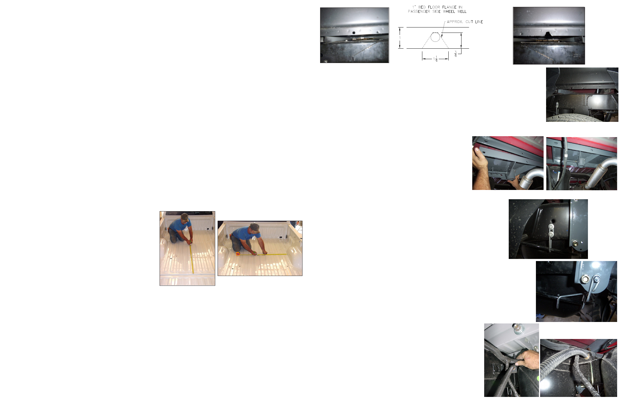
STEP 2
Install the two cross members. They will be installed by sliding them from inside the wheel well, above the tire,
through the gap between the bed and the truck’s frame and across until they span the frame rails. The gap between the
bed and frame is large enough to allow this, but the gap is partially obstructed by a sheet metal flange (about 1 inch in
height) that is hanging down from the bottom of the truck bed floor. A small notch needs to be made in this flange on the
Passenger’s side of the truck. Locate the 7/16” hole in this flange above the axle and enlarge the hole by removing the
metal below the hole so that a notch is created. This will allow the rear cross member to be installed.