Preparing to install, Install socket post, Install companion base – B&W Trailer Hitches Companion Model 3500 User Manual
Page 2: Install pivot arms
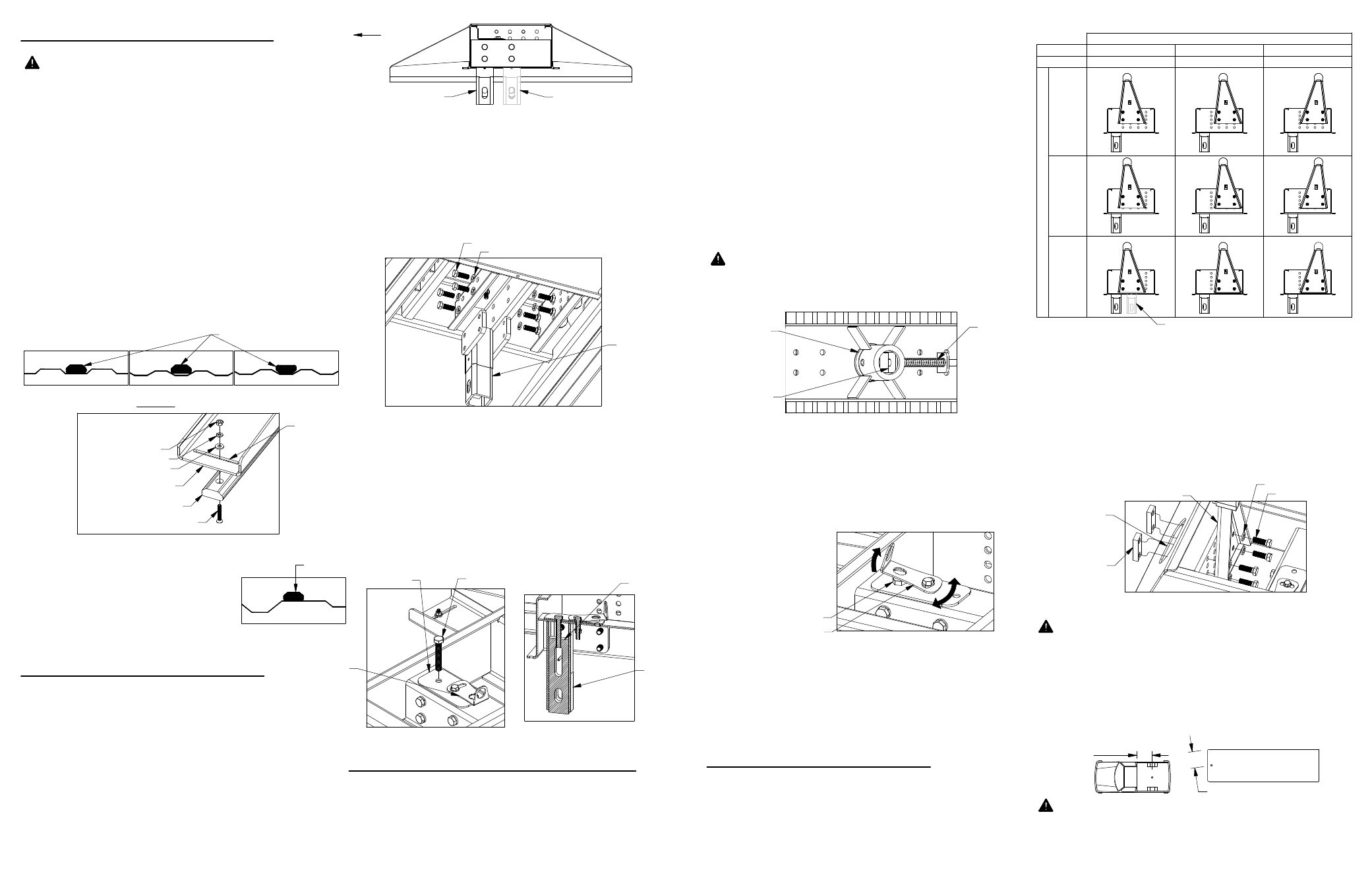
PREPARING TO INSTALL
WARNING: Components of the Companion hitch are
heavy and cumbersome to handle. Failure to use
proper lifting techniques when moving and handling
these parts could result in property damage or
serious injury.
Check that the spacer under the locking bracket is
turned so that the hole in the spacer is positioned over
the socket post. If adjustment is needed, use a tool,
such as a screwdriver, to pry up and rotate the spacer.
Install the 1/2" x 3" cap screw (draw down bolt) into
the top of the Companion base, as shown in figure B3.
Thread the cap screw into the socket adjuster and
hand tighten until the bottom of the slot in the socket
adjuster is even with the bottom of the slot in the post
as shown in figure B4.
Locate the two plastic foot pads. Each pad attaches
to the base through a slot at the end of the base leg.
Before attachment, check the width of your bed rib by
setting the wide face the plastic foot in a bed rib, see
figure A1. If the plastic foot does not reach to the
bottom of the bed rib trough, turn the plastic foot over,
see figure A2 & A3. Locate four 1/4" machine screws,
1/4" flat washers, 1/4" lock washers and 1/4" finish
nuts. Insert the machine screw up through the bottom
of the foot pad through the slot and attach it with a
1/4" flat washer, 1/4" lock washer and a 1/4" finish nut,
see figure A3. Do not tighten hardware at this time, so
that the plastic foot is able to move back and forth in
the slot.
Secure the base to the truck bed by first tightening
the eight 1/2" cap screws attaching the socket post
into the center of the base to 80 ft−lbs. Second,
tighten the 1/2" x 3−1/2" draw−down bolt to 60 ft−lbs.
Lock the draw down bolt in place by swiveling the
locking bracket over the draw down bolt, see figure
C2.
WARNING: Check the latch pin under the truck. Make
sure that the latch pin has passed through both sides
of the socket and that the pin is covered up inside the
socket by the socket adjuster, see figure C1.
Square the Companion base legs with the ribs of the
truck. Position the plastic pads so that they are both
in line with the rib along their entire length. Tighten
the four ¼" nuts holding the pads to the base.
The socket post of the Companion hitch is designed to
have two mounting options. In most truck models, the
gooseneck socket will be forward of the axle and the
companion socket post will install towards the cab of
the truck (position 1). If your socket is located over the
axle due to the frame configuration of your truck, as it
is in the 2013 RAM 3500 trucks, install your socket
post so the post is towards the rear of the truck.
(position 2), see figure B1.
Once you have established in which orientation the
socket post should be installed, locate the socket post
and eight 1/2" cap screws and 1/2" lock washers.
Slide the socket post into the bottom of the
Companion base and attach the socket post to the
base with the eight 1/2" cap screws and lock washers.
See figure B2. Do not fully tighten hardware at this
time.
INSTALL SOCKET POST
Carefully lift and position the Companion base into the
GN hitch socket in the back of the truck bed. Orient
the base so that the large warning label and the
socket post are on or facing the cab side of the truck.
Re−engage the GN latch pin handle in the driver side
fender.
NOTICE: DO NOT lubricate the draw down bolt, the
torque value is for dry threads only.
WARNING: B&W also recommends that you check
the clearance between the bed side and the underside
of the front of the trailer and to allow adequate
clearance for the pitch and roll of the trailer while
towing.
Locate both pivot arms, the four ½" threaded blocks,
eight ½" cap screws, and eight ½" split lock washers.
Place the lock washers over the cap screws. Align the
flat side of the pivot arm flat against the bolt plate and
install four 1/2" cap screws through the holes on the
arm, holding the arm in place. The holes on one side
of the threaded block have a tapered edge for starting
screws. Pass the threaded blocks through the leg and
align the blocks with each set of screws and start each
screw. After all screws are started through the arms,
torque each bolt to 80 ft−lbs.
WARNING: B&W recommends that you check the
clearance between the truck cab and the trailer.
Compare the measurement taken from the center of
the Coupler to the cab, to the measurement taken
from the center of the king pin to the farthest forward
corner point of the trailer. These measurements will
allow you to see how much clearance you will have
between the cab and the trailer while towing and
turning.
1.
3.
2.
1.
3.
4.
5.
6.
1.
2.
INSTALL COMPANION BASE
NOTICE: If truck is equipped with a removable bed liner
or mat, it should be removed or it must be cut to allow the
base to directly connect with the bed. It is acceptable to
install the RV base over a spray−in bed liner.
Check that the bed of the truck is clean, and that all
debris is removed before beginning installation.
INSTALL PIVOT ARMS
Mount the pivot arms using one of the nine different
locations illustrated in Table C1. These nine locations
allow flexibility in coupler height (vertical adjustment)
and distance from the cab (horizontal adjustment).
Choose a location so that your trailer will be as level
as possible and have adequate turning clearance
while towing. See warnings after step 2.
Locate the GN latch pin handle of the Turnoverball™
Gooseneck Hitch in the driver’s side fender well.
Retract the GN latch pin handle all the way to
disengage the pin from ball. Remove the
Turnoverball from the GN hitch receiver socket.
2.
NOTICE: Failure to "lock" the draw down bolt with the
locking bracket will allow the draw−down bolt to
loosen. Property damage may result when the base is
not properly clamped to the truckbed.
NOTICE: Nissan Titan trucks:
Due to the configuration of the bed
ribs on Nisan Titan trucks, it will be
necessary for the foot pad to be
installed on top of a bed rib, see
figure A5.
NOTICE: If the Companion is to be used in conjunction
with a 1257 or 1309 model gooseneck hitch, call the
factory for a post that is compatible with these hitches.
FIGURE A4, Plastic foot pad installation.
FIGURE B2: View of base looking up at the bottom.
FIGURE A3
Narrow rib orientation.
FIGURE A1:
Wide rib orientation.
FIGURE C1: Typical view of Turnoverball
gooseneck center under bed.
FIGURE C2: View of top of base.
FIGURE C2: View looking at passenger
pivot arm mounting location.
FIGURE A2
Incorrect orientation.
V
E
R
T
IC
A
L
A
D
JU
S
T
M
E
N
T
HORIZONTAL ADJUSTMENT
H
IG
H
E
S
T
P
O
S
IT
IO
N
S
(1
8
1/
4"
)
LO
W
E
S
T
P
O
S
IT
IO
N
S
(1
6
1/
4"
)
M
E
D
IU
M
H
E
IG
H
T
P
O
S
IT
IO
N
S
(1
7
1/
4"
)
TABLE C1: Pivot arm position table
Kingpin
3"
behind post
Kingpin
3"
behind post
Kingpin
7"
behind post
Kingpin
1"
behind post
Kingpin
5"
behind post
Kingpin
1"
ahead of post
POSITION 2
POSITION 1
FIGURE B1: Cutaway view of Companion base with
both socket post positions shown.
FIGURE A5:
Titan rib configuration.
FIGURE B3: View of center of base
FIGURE B4: Cutaway
view of center of base.
BASE LEG
PLASTIC FOOT PAD
1/4" MACHINED SCREW
1/4" FLAT WASHER
1/4" LOCK WASHER
1/4" FINISH NUT
SOCKET
PIN
SOCKET
ADJUSTER
SOCKET
POST
1/2" LOCK WASHER
1/2" CAP SCREW
1/2" X 3" CAP SCREW
CENTER OF
COUPLER
TO CAB
KING PIN TO EDGE OF TRAILER
PLASTIC FOOT PAD
FOOT
SLOT
LOCKING BRACKET
1/2" DRAW DOWN BOLT
1/2"
THREADED
BLOCK
HOLE IN
BASE LEG
PIVOT ARM
1/2" LOCK WASHER
1/2" CAP SCREW
POSITION 2
POSITION 2
PLASTIC
FOOT PAD
POSITION 1
CAB SIDE
OF TRUCK
SPACER
LOCKING
BRACKET
SOCKET
POST
SOCKET
ADJUSTER