Before installing, Installation instructions, Application update – B&W Trailer Hitches Turnoverball Model 1062 (Chevrolet_GMC) User Manual
Page 2
STEP FIVE - INSTALL THE CENTER SECTION
Raise the center section into position with the socket top pointed upward, and the latch
pin to the driver’s side. Raise the center section over the differential, and angle it up over
the exhaust pipe until it clears the fuel tank, and then move it back over the fuel tank as
shown. There are fuel lines and wiring coming out of the top of the fuel tank, so you must
avoid damaging those by holding the center section tightly against the bottom of the truck
bed floor while moving it. Insert the socket top into the 4-inch hole in the floor. If you are
using an overhead lifting device, attach it to the latch pin, and apply a small amount of up-
ward pressure to the truck bed floor, to make bolting easier. Move the front bar against the
center section sliding the pressed bolt into the matching hole in the center section. Install
two of the 2 1/4” x 1/2” bolts through the bar and into the center section while placing a
flat washer, lock washer, and nut on the bolt threads. Next thread four 1 1/2” bolts with flat
and lock washers through the center section and into the rear bar. Shift the bar sideways
until it is centered across the frame. Also twist the assembly so that it is parallel with the
bed crossmembers and tighten all center section fasteners at this time.
STEP SIX - INSTALL SIDEPLATES
Next install the sideplates. The driver’s sideplate is shown, with the bent flange to the
front, and the large holes to the rear. Attach the two pieces of the sideplate together
with ½” carriage bolts. The carriage bolts should be inserted into the square holes from
the backside of the sideplates and fastened using a lock washer and nut on each bolt.
This can be completed before installing on the frame rail.
Attach the flange on the sideplate to the front bar by placing a 1/2” x 2 1/4” bolt through
the bar and sideplate; secure with a flat washer, lock washer and nut.
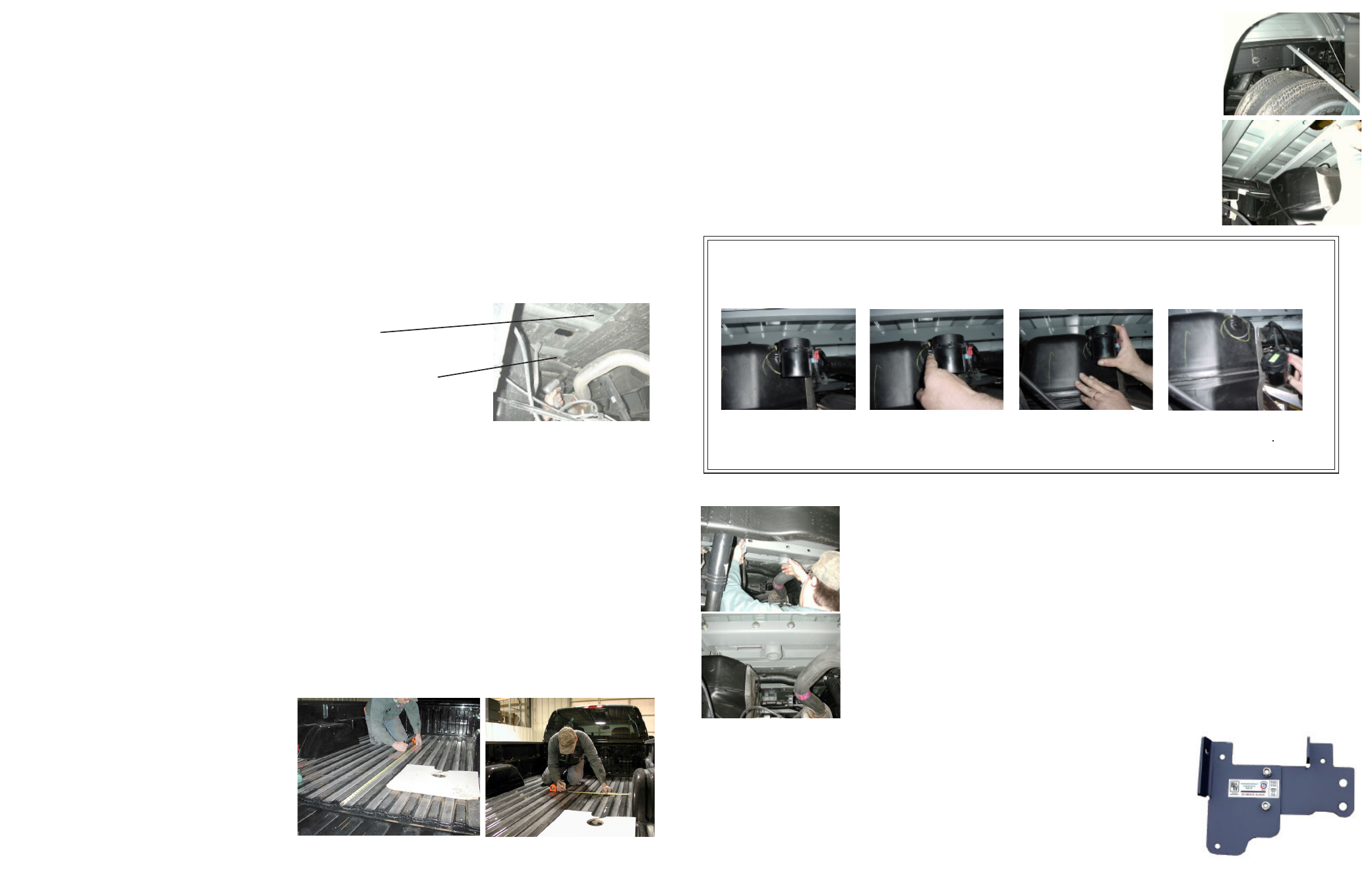
Step 1:
Locate the fuel valve.
Step 2:
Disengage the lock-
ing pin.
Step 3:
Slide fuel valve from
bracket.
Step 4:
Install Turnoverball™
Center Section.
APPLICATION UPDATE:
The new fuel valve mounted on the rear of the fuel tank on 2004 and newer model trucks equipped with gas
engines, will make it more difficult to install the Turnoverball
TM
center section. This fuel valve can be easily
removed and replaced to ease installation. Please follow the following instructions:
Step 5: Replace fuel valve to bracket on fuel tank
.
STEP FOUR - INSTALL CROSSMEMBERS
The next step is to install the two crossmembers. They install through the gap between the
bed and the frame. The front crossmember can be identified by the bolt pressed into one
hole. Install the front bar by sliding it across the frame rails between the two bed cross
members where the four inch hole has been cut. Slide the bar in and center between the
frame rails. Next rotate the bar so that the pressed bolt is above the fuel tank and the threads
are facing toward the rear of the truck. Now it can be pushed forward on the frame toward
the front bed crossmember, on the higher part of the frame. It is difficult to rotate the bar
on the higher frame, so be sure to rotate it before moving it forward. The rear crossmem-
ber installs between the double bed crossmembers. Push the bar in lying horizontal until
centered and then rotate it to vertical, making sure that the threaded holes are positioned
at the bottom of the bar. Position this bar right behind the bed crossmember that is closest
to the 4” hole in the truck bed. The holes in this bar are threaded to receive ½ inch bolts.
Measure from the back end (tail gate end) of the truck bed floor by hooking a tape measure over the back
of the sheet metal and marking the floor at the correct measurement. Center the measurement between
the fender wheel wells. This location is critical
to the correct installation of this hitch, so mea-
sure, mark and saw carefully. If the truck has
a plastic bed liner, you may drill through both,
but it is more difficult to accurately locate the
midpoint between the fender wheel wells, and
to be sure that the bed liner does not move
while sawing the hole. Make a 4 inch hole at
this location using a four inch hole saw, or by
marking a 4 inch circle and cutting it out with a
saber saw equipped with a metal cutting blade.
Truck Type: Long bed single & dual wheeled 1 Ton.
Ball Location: 49 1/2” from the back of the bed.
STEP THREE - MARKING AND CUTTING 4 INCH HOLE IN TRUCK BED
Begin by verifying and measuring the correct hole location in the truck bed floor.
BEFORE INSTALLING
OVERHEAD LIFTING DEVICE
An overhead-lifting device, such as chain falls, engine hoist, or cable come-a-long, can be used to lift the center section of
the hitch in place. Lower a loop of rope or chain through the 4” hole in the truck bed floor and attach it to the latch pin in the
round hitch receiver tube in the center section. Use the lifting device to raise the center section until the round hitch receiver
tube that protrudes from the center section fits in the 4” hole in the truck bed floor. Maintaining upward pressure may facilitate
fastening the crossmember to the center section, especially if the truck bed floor has been distorted downward from heavy
use. If you use an overhead-lifting device, it should be disconnected before squaring the center section across the frame,
installing the sideplates and torquing fasteners.
WARNING
Most trucks have FUEL LINES and/or BRAKE LINES and/or ELECTRICAL WIRES located along the frame rails where B&W Turn-
overball™ hitches install. Carefully examine the location of fuel lines, brake lines and electrical wires BEFORE INSTALLATION.
Be certain you will not damage fuel lines, brake lines or electrical wires when positioning hitch components, drilling holes,
tightening fasteners, and lifting and lowering the truck bed. The fuel tank vent, located on top of the gas tank, can be easily
damaged during the installation of the hitch components. Care must be taken when positioning the front crossmember and
center section components. We recommend removing the bed bolts on the driver’s side and lifting the bed to give you more
clearance during installation of the hitch parts under the bed floor.
INSTALLATION INSTRUCTIONS
STEP ONE - REMOVE SPARE TIRE AND HEAT SHIELD
The heat shield under the bed floor must either be removed or a section cut out
for the hitch assembly to be installed.
A) Remove the heat shield from in front of the back crossmember.
B) Remove the heat shield from the back of the crossmember located near
the front of the wheel well.
STEP TWO - REMOVE EXHAUST BRACKET
To ease installation of the center section it is necessary to remove the lower exhaust bracket. Simply pull the
hanger rod out of the rubber bracket hole, a 6” to 8” wood block can then be positioned between the exhaust pipe
and frame of the truck. This will increase your clearance between the top of the exhaust pipe and the bottom of
the truck bed floor. (Caution: Exhaust pipe may be hot).