Model 1111, Before installing, Attention – B&W Trailer Hitches Turnoverball Model 1111 (Ford) User Manual
Page 2: Turnoverball, Gooseneck hitch installation instructions, Call or email us for installation support, Step 12 - re-engage latch pin handle, Step 11 – re-attach exhaust, Step 9 – install latch pin release handle, Overhead lifting device
Model 1111
Copyright 2013
B&W Custom Truck Beds, Inc.
ALL RIGHTS RESERVED
1111 - 08 28 2013
www.turnoverball.com
Call or Email us for Installation Support
800.248.6564
Turnoverball
TM
Gooseneck Hitch Installation Instructions
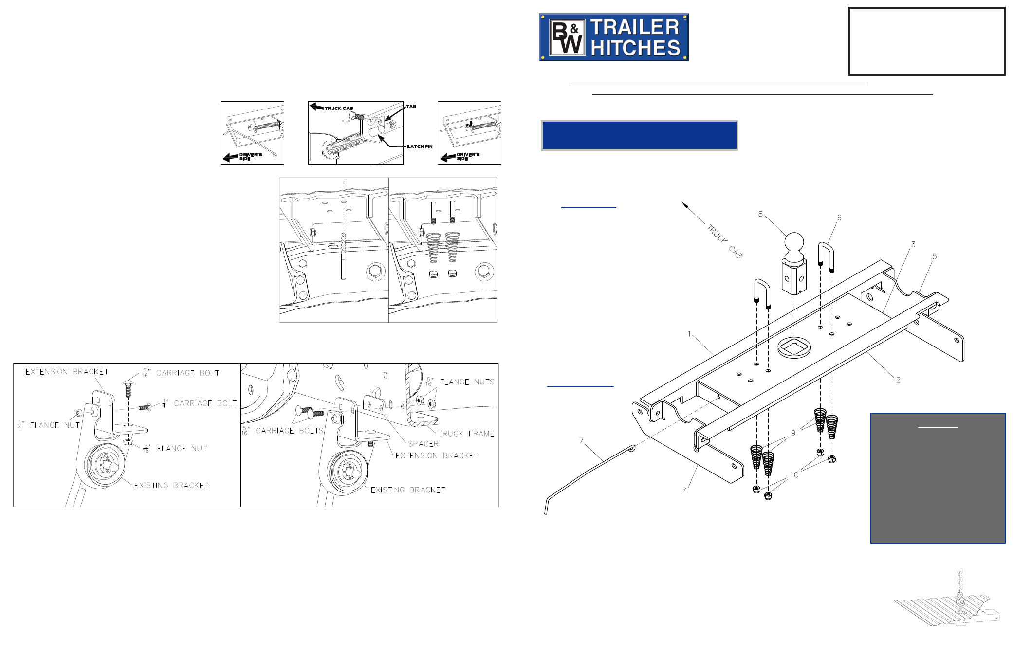
Parts List
1 - Front Crossmember
2 - Rear Crossmember
3 - Center Section
4 - Driver’s Side Sideplate
5 - Passenger’s Side Sideplate
6 - Safety Chain U-Bolts
7 - Latch Pin Handle
8 - 2-5/16” Ball
9 - Springs
10 - 1/2” Lock nuts
STEP 12 - RE-ENGAGE LATCH PIN HANDLE
Retract the latch pin by pulling the handle all the way out until it stops and then rotate it clockwise. Place the 2-5/16” Ball in the
hitch receiver. Engage the latch pin by rotating the handle counterclockwise. Be certain the latch pin passes through the holes in
the 2-5/16” Ball and fully engages through the hitch receiver. Remove and grease the square base of the 2-5/16” Ball.
B&W Trailer Hitches
1216 HWY 224 / PO Box 186
Humboldt, KS 66748
P:620.473.3664
F:620.473.3766
Ford Super Duty 2011-2014
3/4 & 1 Ton, Short & Long Bed
F-450 w/Factory Installed Bed
STEP 10 – INSTALL SAFETY CHAIN U-BOLTS
To install the safety chain U-bolts, it is necessary to drill four ½” holes
through the truck bed floor. Drill the holes from beneath the truck,
through the two holes located on each side and closest to the round
receiver tube in the center section. This will locate the safety chain
U-bolt in the lowest point of the floor corrugation. After you drill the
four holes, clean the burrs from around the holes in the top of the
bed, then drop a U-bolt through each pair of holes. Place a spring and
lock nut on each of the four legs. Tighten the nuts until flush with the
bottom of the U-bolts.
STEP 13 - Reinstall the spare tire heat shield and spare tire.
Diagram 11.1. Attach the supplied extension bracket to the
existing tail pipe bracket.
Diagram 11.2. Attach the supplied extension bracket to the frame,
using the same hole used by the factory bracket and the hole directly
right of it. Not all truck models will have the hole directly to the
right. In this case, attaching the bracket with one bolt is sufficient.
STEP 11 – RE-ATTACH EXHAUST
In
pickups equipped with a diesel engine, the exhaust may have to be lowered to allow clearance for the Turnoverball™ Hitch.
See Diagrams 11.1 and 11.2.
STEP 9 – INSTALL LATCH PIN RELEASE HANDLE
WARNING: LATCH PIN WILL NOT FUNCTION PROPERLY IF HANDLE IS NOT INSTALLED CORRECTLY.
Install the handle from underneath the truck by inserting it through the slot in the end of the center section toward the driver’s side
rear tire as shown. Attach the handle to the latch pin as shown with the handle on the “cab side” of the square tab welded to the pin.
The head of the bolt must be on the handle side, and the
lock nut must be on the tab side. The tab is welded to the
pin in an offset position so that the handle will be lined
up over the center of the pin. If the handle is fastened
to the other side of the tab, the handle will not function
properly. When installed correctly the latch pin may be
disengaged from the ball by pulling on the handle from the
driver’s side wheel well and rotating the handle clockwise.
Hardware Kit
2 ea. - 3/4” X 2 1/2” Bolts
14 ea. - 1/2” X 1 1/2” Bolts
3 ea. - 5/16” X 1 Carriage Bolts
1 ea. - 1/4” X 3/4” Carriage Bolt
1 ea. - 3/4” Flat Washer
1 ea. - 3/4” Rectangular Washer
14 ea. - 1/2” Flat Washers
2 ea. - 3/4” Lock Washers
14 ea. - 1/2” Lock Washers
2 ea. - 3/4” Nuts
14 ea. - 1/2” Nuts
3 ea. - 5/16” Flange Nut
1 ea. - 1/4” Flange Nut
2 ea. - Pipe Spacers
1 ea. - Exhaust Bracket
1 ea. - Exhaust Spacer
1 ea. - Sensor control module
relocation bracket.
Safety Chain Kit
2 ea. - 1/2” U-Bolts
4 ea. - 1/2” Lock Nuts
4 ea. - Springs
An overhead-lifting device, such as chain falls, engine hoist, or cable come-a-long, can be used
to lift the center section of the hitch in place. Lower a loop of rope or chain through the 4” hole
in the truck bed floor and attach it to the latch pin in the round hitch receiver tube in the center
section. Use the lifting device to raise the center section until the round hitch receiver tube that
protrudes from the center section fits in the 4” hole in the truck bed floor. Maintaining upward
pressure may facilitate fastening the crossmember to the center section, especially if the truck
bed floor has been distorted downward from heavy use. If you use an overhead-lifting device,
it should be disconnected before squaring the center section across the frame, installing the
sideplates and torquing fasteners.
BEFORE INSTALLING-
OVERHEAD LIFTING DEVICE
Attention:
If you intend to use a Companion 5th Wheel
RV Hitch in a 2011 Ford Truck, please call
us at 800-248-6564 for a foot pad kit that
fills voids in the truck bed rib pattern. Using
the Companion on a 2011 Ford without the
supplemental kit could result in damage to
the bed.
NOTE: We recommend reading instructions before beginning the installation.
WARNING: The tow vehicle’s towing capacities should under NO circumstances be exceeded.
STEP 8 – TIGHTEN HARDWARE
1. Tighten the center section to cross member bolts to 80 ft pounds. 2. Check to ensure the assembled center section is square with
the frame. 3. Tighten the ¾” side plate bolts to 120 ft pounds. 4. Tighten the 1/2” side plate bolts to 80 ft pounds. 5. Tighten the
side plate to angle bolts to 80 ft pounds.