Preparing to install, Install slider base, Install pivot arms – B&W Trailer Hitches Companion Slider Model 3400 User Manual
Page 2: Install coupler, Attaching trailer, Pull test, Unattaching trailer, Uninstall hitch
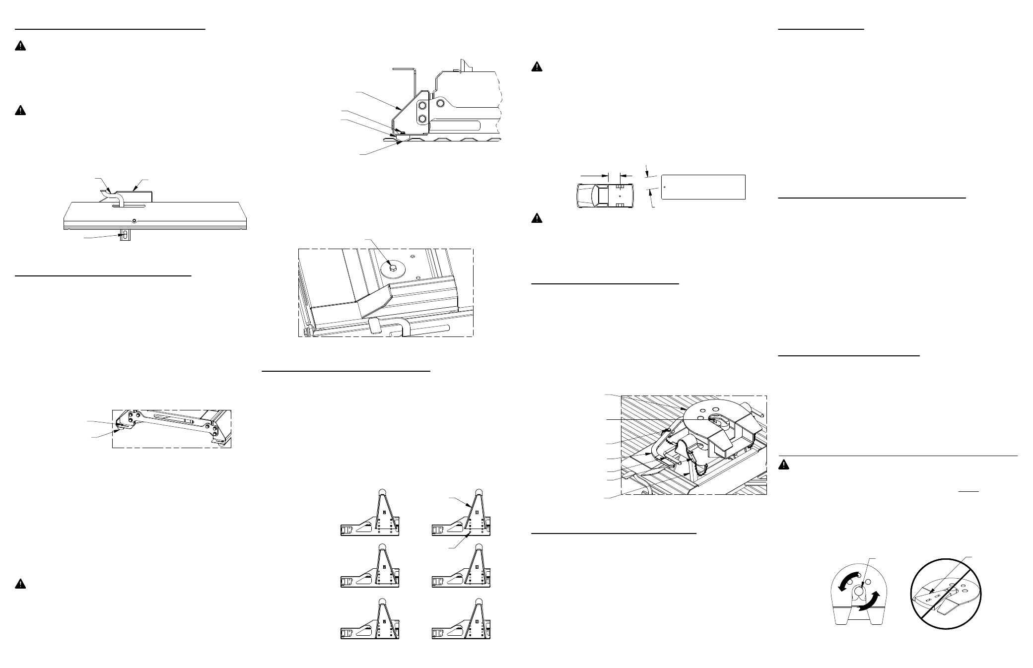
FIGURE A1; View of driver side of Slider Base.
FIGURE C1; Cut away view of
Slider Carriage arm positions.
FIGURE B3; Back view of the
driver side leg of the Slider Base.
FIGURE B4; View looking into the top of the Slider Base.
FIGURE D1; View of Slider Base
and Coupler Head assembled.
FIGURE E1;
Top view of coupler head.
FIGURE B1; View looking at the Slider Base from the cab of the truck .
PREPARING TO INSTALL
WARNING: Components of the slider hitch are heavy
and cumbersome to handle. Failure to use proper
lifting techniques and an adequate amount of people
when moving and handling these parts could result in
property damage or serious injury.
WARNING: Whenever the slider base is being
moved, the slider handle must be in the locked
position, and the carriage must be unable to slide,
see figure A1. Failure to ensure that the handle is in
the locked position can lead to property damage, or
serious injury.
6.
NOTICE: If truck is equipped with a removable bed
liner or mat. It should be removed or it must be cut to
allow the base to directly connect with the bed. It is
acceptable to install the RV base over a spray in bed
liner.
Check that the bed of the truck is clean, and that all
debris is removed before beginning installation.
Loosen the four ¼" cap screws securing the
polyurethane pads on either side of the slider hitch,
see figure B1.
Locate the GN latch pin handle of the Turnoverball™
Gooseneck Hitch in the driver’s side fender well.
Retract the GN latch pin handle all the way until it
stops and then rotate it clockwise. Remove the
Turnoverball from the GN hitch receiver socket.
With the help of 2 or 3 people, carefully lift and
position the slider base into the GN hitch socket in the
back of the truck bed. Re−engage the GN latch pin
handle by turning it counter−clockwise.
WARNING: Check the latch pin under the truck. Make
sure that the latch pin has passed through both sides
of the socket and that the pin is covered up inside the
socket by the socket adjuster, see figure A1. If the pin
is visible inside the GN hitch socket retract the GN
latch handle and use the Draw−Down bolt to adjust the
socket adjuster.
2.
1.
INSTALL SLIDER BASE
3.
Secure the base of the Slider to the truck bed by
tightening the 1/2" x 3−1/2" draw−down bolt to 80 ft−lbs,
see figure B4
WARNING: DO NOT lubricate the draw down bolt, the
torque value is for dry threads only.
INSTALL PIVOT ARMS
Mount the pivot arms using one of the six different
locations illustrated in figure C1. These six locations
allow flexibility in coupler height and distance from the
cab. Choose a location so that your trailer will be as
level as possible and have adequate turning clearance
while in the towing position (with the slider in the
foward position). See warnings after step 2.
1.
INSTALL COUPLER
With the flat side of the Pivot arm flat against the bolt
plate in the slider base, install four 1/2" x 1−1/2" bolts
and four 1/2" split lock washers for each arm. Torque
each bolt to 80 ft−lbs.
WARNING: B&W recommends that you check the
clearance between the truck cab and the trailer in both
the Towing position and the maneuvering position.
Compare the measurement taken from the center of
the Slider Coupler to the cab, to the measurement
taken from the center of the king pin to the farthest
forward corner point of the trailer. These
measurements will allow you to see how much
clearance you will have between the cab and the
trailer while towing and turning.
WARNING: B&W also recommends that you check
the clearance between the bed side and the underside
of the front of the trailer and to allow adequate
clearance for the pitch and roll of the trailer while
towing.
Lubricate the polyurethane bushings on top of pivot
arms with high grade lithium grease (available at your
local hardware/automotive store). Place the coupler
over the pivot arms. (The saddle handles should be
parallel with the Slider Base in the latched position.)
Place the saddle lock pins through the saddle, then
insert the hairpins through the holes in the end of the
saddle lock pins to secure the coupler to the pivot
arms, see figure D1
Remove the coupler cam handle safety pin and rotate
the cam handle to the open position. Adjust the height
of the 5th wheel trailer so that the king pin plate is
slightly lower than the top of the Coupler. Back the
truck towards the trailer, centering the trailers king pin
in the Coupler, until the king pin has engaged the
jaws. Ensure that the Coupler cam handle has
completely closed before inserting the cam handle
safety pin through the cam handle and the coupler.
Hook up brake and lighting connections before towing.
ATTACHING TRAILER
2.
Have the truck stationary with the emergency brake
on, the trailer wheels blocked and landing gear still
resting firm on the ground supporting the weight of the
trailer. Make sure no one is between the truck and
trailer, return to the cab of the truck. Release the
emergency brake and apply the trailer brakes. Try to
pull the trailer forward with the truck. If the trailer is
properly hooked up, the wheel blocks and trailer
brakes should not allow the truck to move forward. If
trailer is not hitched correctly, the trailer will separate
from the truck. However, with the landing gear resting
firmly on the ground, it will support the trailer and not
allow it to drop or fall on the truck sides.
PULL TEST
Lower landing gear and block the trailer wheels.
Raise the trailer until the tongue weight is removed
from the truck. Then, unpin the Coupler handle and
rotate to the open position to unlatch the jaws. If the
jaws do not open, readjusting the landing gear may
relieve pressure and allow them to open. Use the
safety pin to lock the handle in the open position and
when you are sure that the landing gear will support
the trailer, move the truck forward to release the jaws
from the kingpin. The jaws will always open when the
pressure of the trailer is taken off the Coupler as the
truck pulls away.
UNATTACHING TRAILER
To uninstall the Slider hitch, remove the Saddle lock
pins, grab the saddle handles and lift to remove the
Coupler from the pivot arms. To remove the Slider
base, loosen the draw down bolt and retract the
Turnoverball gooseneck latch pin handle all the way
out until it stops and then rotate it clockwise. With the
help of 2 or 3 people, carefully lift and position the
slider base out of the Goosenech hitch socket.
WARNING: Do not use the Slider 5th wheel hitch with
any device that changes the location of the king pin
pivot point. The king pin on your trailer must rotate in
the jaws of the Slider Coupler, see figure E1.
Preventing the king pin from rotating within the jaws of
the Slider Coupler with a wedge, see figure E2, or any
other device, such as a Reese Sidewinder or Reese
Revolution , could result in property damage, serious
injury or death.
UNINSTALL HITCH
4.
5. Square the Slider base legs with the ribs of the truck.
Position the polyurethane pads so that they are both in
a bottom rib along their entire length, See figure B3.
Tighten the four ¼" bolts holding the pads to the base.
®
®
Reese is a registered trademark of Cequent performance products.
®
BED FLOOR TO TOP
OF COUPLER
POSITION
CLOSEST TO CAB
POSITION FARTHEST FROM
CAB (ARMS REVERSED)
HIGHEST
POSITION
(19")
MIDDLE
POSITION
(18")
LOWEST
POSITION
(17")
SLIDER HANDLE
IN LOCKED POSITION
SLIDER CARRIAGE
Polyurethane Pad
Slider Base Leg
Bottom of Bed Rib
1/4" Bolt
Draw−Down Bolt
COUPLER CAM HANDLE
SADDLE HANDLES
COUPLER CAM
HANDLE SAFETY PIN
SADDLE LOCK PINS
COUPLER JAWS
WEDGE
KING PIN
PIVOT POINT
FIGURE E2;
Coupler Head with locking wedge.
POLYURETHANE
PADS
1/4" BOLT
CENTER OF
COUPLER
TO CAB
COUPLER
PIVOT ARM
PIVOT ARM
BOLT PLATE
KINGPIN TO EDGE OF TRAILER
SOCKET ADJUSTER