Installation instructions, Assembly instructions continued – B&W Trailer Hitches RVK3000 User Manual
Page 2
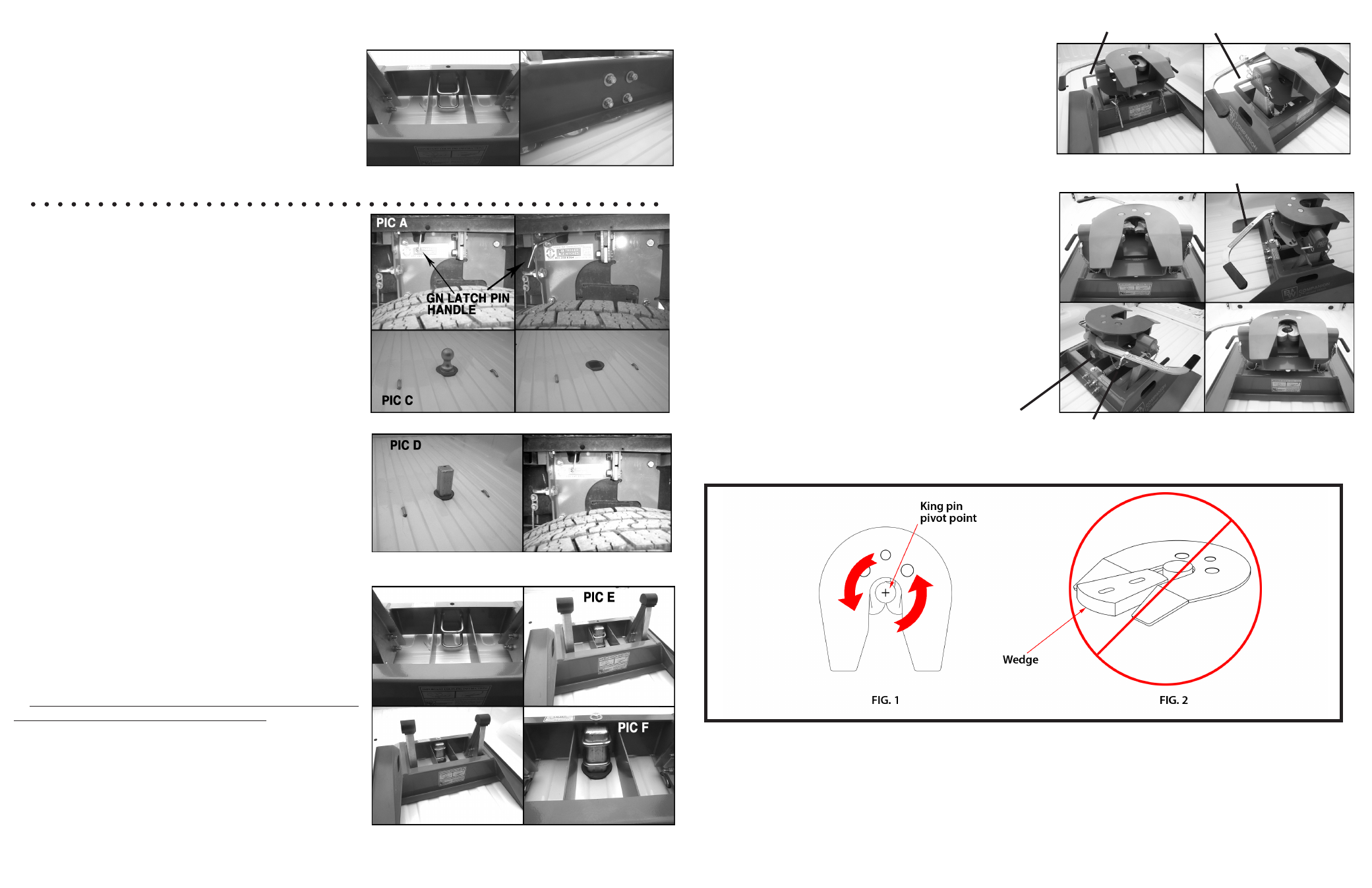
STEP 1: REMOVE BALL
Locate the GN latch pin handle (PIC A) of the
Turnoverball™ gooseneck hitch in the driver’s side fender
well. Retract the GN latch pin handle all the way out until
it stops and then rotate it clockwise. (PIC B) Remove the
Turnoverball™ (PIC C) from the GN hitch receiver socket.
STEP 2: INSTALL POST
Install the RV Post (J) in the GN hitch receiver
socket with the threaded hole towards the cab. (PIC D)
After the RV post is placed into the GN hitch receiver
socket, engage the GN latch pin by rotating the handle
counterclockwise.
STEP 4: INSTALL COUPLER
Lubricate the polyurethane bushings with high
grade lithium grease (available at your local hard-
ware/automotive store). Place the RV coupler so it
saddles the RV pivot arms. (The RV saddle handles
should be parallel with the RV Base in the latched
position.) Place the RV saddle lock pins through the
RV saddle, then insert the hairpins through the holes
in the end of the RV saddle lock pins to secure RV
coupler to the RV pivot arms.
STEP 5: ATTACHING TRAILER
Remove the RV cam handle safety pin and ro-
tate the RV cam handle to the open position. Adjust
the height of the 5th wheel trailer so that the king pin
plate is slightly lower than the top of the Companion
RV coupler. Back the truck towards the trailer, center-
ing the trailers king pin in the RV Companion coupler,
until the king pin has engaged the jaws. Ensure that
the RV cam handle has completely closed before in-
serting the RV cam handle safety pin through the RV
cam handle and the RV coupler. Hook up brake and
lighting connections before towing.
STEP 3: INSTALL BASE
Note: If truck is equipped with a removable bed liner
or mat. It should be removed or it must be cut to al-
low the base to directly connect with the bed. It is
acceptable to install the RV base over a spray in bed
liner.
Place the RV Base over the RV post so that the
U-bolts wrap around the RV post. (PIC E) Then place a
½” washer (K) on the ½” x 3” draw-down bolt (D), insert
the bolt through the hole in the top flange of the RV base
and hand-thread the draw-down bolt into the RV Post.
**NOTE: DO NOT lubricate the draw down bolt or U-
bolts, the torque value is for dry threads. Square the RV
base legs with the ribs of the truck bed and then tighten
the ½” x 3” draw-down bolt to 40 ft-lb. Next, tighten
the two u-bolts to 80 ft-lb. to secure the RV Base to the
RV Post. It is very important that the draw-down bolt is
tightened before the U-bolts are tightened. When the RV
Base is installed correctly, the RV Post should have a ¼”
to 1” gap between the RV Post and the RV Base where
the draw-down bolt attaches.(PIC F) Also, you should
not be able to disengage the latch pin in the wheel well
when the base is installed correctly.
ASSEMBLY INSTRUCTIONS CONTINUED
Installation Instructions
Place the U-bolts (G) from the inside of the RV
base out through the existing holes in the RV base. Once
inserted place a 5/8” flat washer (E) and a 5/8”lock
nut (F) on each leg of the U-bolts, leaving them loose
enough to slide over the RV post at a later time.
STEP TWO - INSTALL U-BOLTS
RV SADDLE HANDLES
RV CAM HANDLE
RV CAM HANDLE
SAFETY PIN
PIC B
GREASE ZERK
ON SADDLE
WARNING:
Do not use the Companion
TM
5
th
wheel hitch with any device that changes the location of the king pin pivot
point. The king pin on your trailer must rotate in the jaws of the Slider Coupler, see figure 1. Preventing
the king pin from rotating within the jaws of the Coupler with a wedge, see figure 2, or any other device,
such as a Reese
®
Sidewinder or Reese
®
Revolution, could result in property damage, serious injury or death.
Reese
®
is a registered trademark of Cequent performance products.