Installation instructions – B&W Trailer Hitches Turnoverball Model 1316 (Dodge) User Manual
Page 2
STEP 3
With the latch pin on the driver’s side and the socket offset
to the front of the truck, raise the center section over the
differential and in between the cross members. Push the
center section up to the floor while guiding the ring into the
four inch hole in the truck bed. Thread four of the 1-1/2”
bolts with a lock and flat washer into the front bar from
inside the center section leaving them loose at this time.
Next with the rear angle against the rear of the center sec-
tion install three 1-1/2” bolts through the center section
and angle securing with a lock and flat washer on each.
DO NOT fully tighten at this time.
STEP 4
The sideplates will have to be installed with the center
section bolts still loose, so that the sideplates can be posi-
tioned between the bar and angle. With the long flange to
the front , place the side plate between the cross members
and thread a 1-1/2” bolt with a flat and lock washer into the
bar. Install the bolt with two flat washers and a lock washer
and nut through the sideplate ear and angle. Repeat this
procedure on the passenger side.
WARNING
Most trucks have FUEL LINES and/or BRAKE LINES and/or ELECTRICAL WIRES located along the frame rails where
B&W Turnoverball™ hitches install. Carefully examine the location of fuel lines, brake lines and electrical wires BE-
FORE INSTALLATION. Be certain you will not damage fuel lines, brake lines or electrical wires when positioning hitch
components, drilling holes, tightening fasteners, and lifting and lowering the truck bed. The fuel tank vent, located
on top of the gas tank, can be easily damaged during the installation of the hitch components. Care must be taken
when positioning the front crossmember and center section components. We recommend removing the bed bolts on
the driver’s side and lifting the bed to give you more clearance during installation of the hitch parts under the bed floor.
WARNING
On Short bed trucks, BEFORE INSTALLING THIS HITCH, check for adequate turning clearance between front of all of
your trailers and the truck cab.
WARNING
DO NOT invert the ball in the socket when carrying heavy loads on 2 wheel drive trucks. The ball may hit the top of
the differential. Remove the ball from the socket before loading. A plug for the socket is available from B & W.
GENERAL INFORMATION
The 2002-2006 Dodge 1500 long and short bed truck has a tubular frame, instead of the traditional “C” shaped channel
frame. The Turnoverball™ gooseneck hitch for this truck clamps to the frame and installation is accomplished without
any welding, drilling, or modification of the truck frame.
INSTALLATION INSTRUCTIONS
STEP 1A: LONG BED INSTALLATION
Begin by marking the location for the hole in the truck bed floor. Measure from the back
end of the truck bed floor by hooking a tape measure over the back of the sheet metal and
mark the floor at 47 5/8” and centered between the wheel wells. This location is critical to
the correct installation of this hitch, so measure, mark, and saw carefully.
STEP 1A: SHORT BED INSTALLATION
Begin by marking the location for the hole in the truck bed floor. Measure from the back
end of the truck bed floor by hooking a tape measure over the back of the sheet metal and
mark the floor at 45 3/4” and centered between the wheel wells. This location is critical to
the correct installation of this hitch, so measure, mark, and saw carefully.
STEP 1B:
If the truck has a plastic bed liner, you may drill through both, but it is more difficult to
accurately locate the midpoint between the wheel wells, and to be sure that the bed liner
does not move while sawing the hole. Make a 4 inch hole at this location using a four inch
hole saw, or by marking a 4 inch circle and cutting it out with a saber saw equipped with a
metal cutting blade.
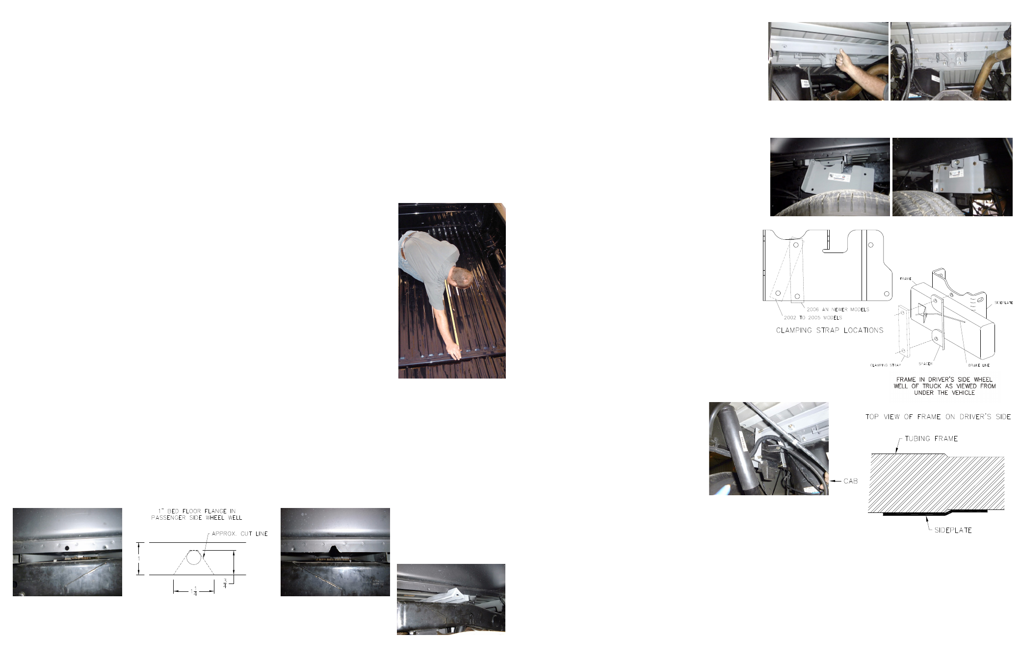
STEP 2
Install the two crossmembers. They will be installed by sliding them from inside the wheel well, above the tire,
through the gap between the bed and the truck’s frame and across until they span the frame rails. The gap between
the bed and frame is large enough to allow this, but the gap is partially obstructed by a sheet metal flange (about 1
inch in height) that is hanging down from the bottom of the truck bed floor. A small notch needs to be made in this
flange on the Passenger side of the truck. Locate the 7/16 hole in this flange above the axle and enlarge the hole
by removing the metal below the hole so that a notch is created. This will allow the crossmembers to be installed.
(see pictures below)
Install the angle iron first. On 2002 though 2005 model trucks the angle leg with the notches should face the rear of
the truck when installing though the notch. On 2006 and newer model trucks the angle leg with the notches should
face the front of the truck when installing though the notch. Hold the angle in an inverted “V” position, and push the
angle across the frame using the notch for clearance at the apex of the angle. With the angle
spanning the frame, move it rearward toward the bed crossmember. Repeat this procedure
with the 1x2 bar with threaded holes. With the bar spanning the frame turn it so that it is
in a vertical position and push the bar forward until it is against the front cross member.
STEP 5
Attach the sideplates to the frame. On 2002 though 2005
model trucks the top front and lower front holes will be
used. On 2006 model trucks the top front and middle
lower holes will be used (see diagram). Install the 1/2”
x 4-1/2” bolts though the holes in sideplates above and
below the frame using the correct holes per year of truck
as stated above. Install the clamping straps on the inside
of the frame over the bolts. On 2006 model trucks a brake
line spacer will need to be added on the drivers side front
before the clamping strap is installed (see diagram). This
will allow the needed clearance between the frame and
clamping strap for the brake line. On the 2002 though
2005 model trucks the clamping strap will install between
the brake line and frame. Secure the clamping straps with
lock washers and nuts. Hand tighten until snug.
STEP 6
The sideplates have a double bend offset
near the rear clamping bolts that will engage
the offset in the truck frame, and create a
wedging lock to prevent the hitch from slid-
ing forward on the frame. Before the final
bolt tightening, position the sideplate so
that the offset in the sideplate is mated
against the offset in the frame, but not
riding up on it so that there would be a
gap between the clamping flange and
the frame. Install the wedging “J” bolts in the frame hole in front
of the sideplate and through the hole in the sideplate front flange,
and install the lock washer and nut. At this time, tighten this nut
only enough to achieve the correct contact between the frame
and sideplate offsets. Loosely install all of the remaining hardware in
the center section.
STEP 7
Tighten the hitch hardware in the following sequence. Tighten the rear sideplate clamping bolts and then the front
sideplate clamping bolts to 60 ft-lbs. of torque. Tighten them slowly, alternating from the top bolt to the bottom so that
they tighten evenly. Also make certain that the bolts are perpendicular (90 degrees) to the truck frame so that the bolts
will not loosen later. Center the front bar crossmember across the frame and tighten bolts to the sideplate. Tighten
the center section bolts to the front bar to 90 ft.-lbs. of torque. Center the angle iron across the frame, and tighten
the bolts to the sideplates and to the center section, also to 90 ft.- lbs. Tighten the “J” bolts to 40 ft. lbs. of torque.