Model 1007r, Before installing, Turnoverball – B&W Trailer Hitches Turnoverball Model 1007 (Chevrolet_GMC) User Manual
Page 2: Gooseneck hitch installation instructions, Call or email us for installation support
www.turnoverball.com
Call or Email us for Installation Support
Turnoverball
TM
Gooseneck Hitch Installation Instructions
STEP TWELVE - INSTALL SAFETY CHAIN U-BOLTS
To install the safety chain U-bolts it is necessary to drill four 1/2” holes
through the truck bed floor. Drill the holes from beneath the truck, through
the two holes located on each side and closest to the round receiver
tube in the center section. This will locate the safety chain U-bolt in
the lowest point of the floor corrugation. Drop a U-bolt through each
pair of holes from the topside of the truck bed floor. Place a spring and
lock nut on each of the four legs. Tighten the lock nuts until flush with
the bottom of the U-bolts.
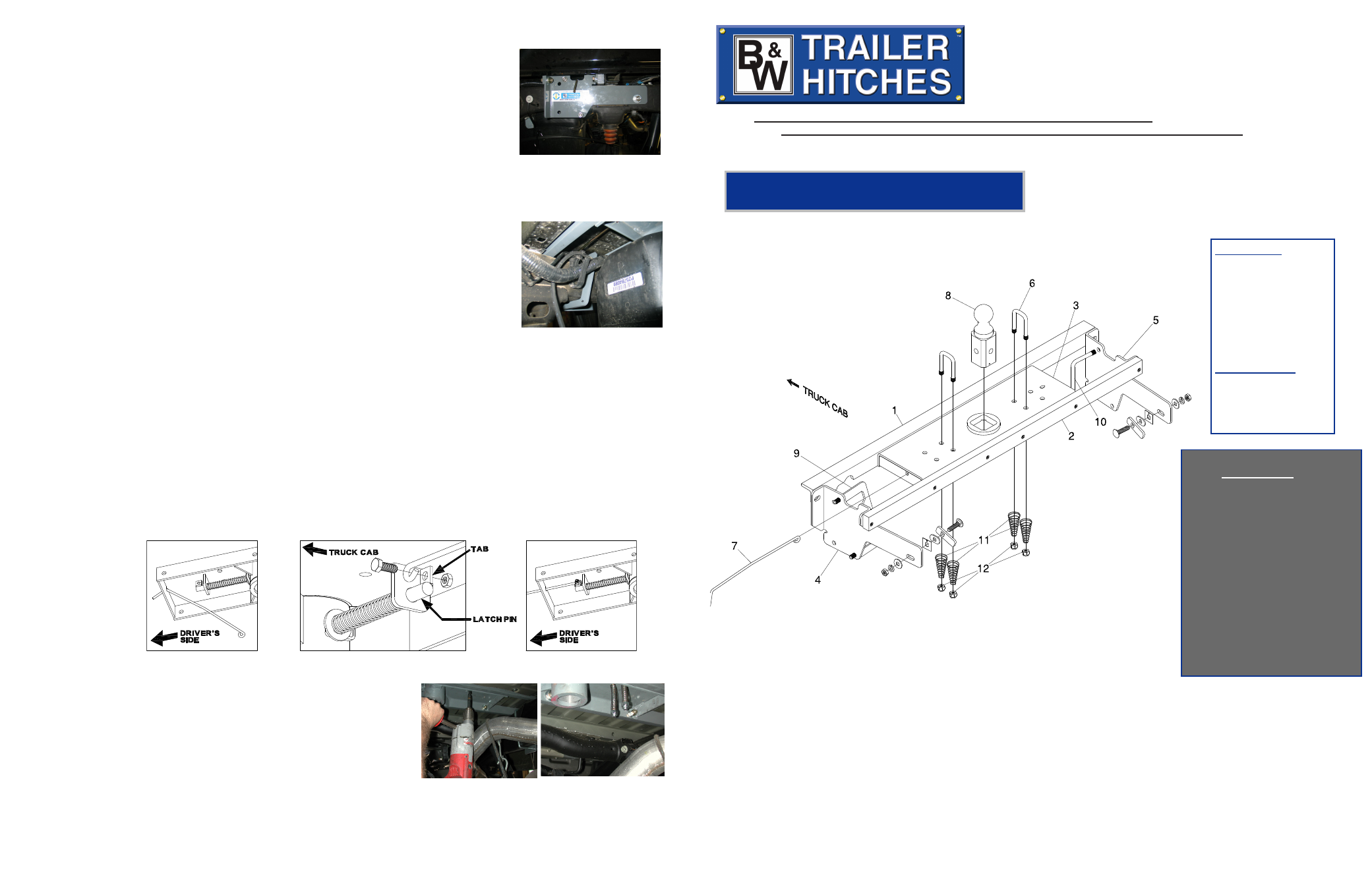
Parts List
1) Front Crossmember
2) Rear Crossmember
3) Center Section
4) Left Sideplate
5) Right Sideplate
6) Safety Chain U-Bolts
7) Latch Pin Handle
8) 2-5/16”Ball
9) Sideplate Clamp
10) 4 3/16” x 5 1/2” U-Bolt
11) Springs
12) 1/2” Lock nut
Model 1007R
STEP THIRTEEN- REPLACE THE EXHAUST BRACKET
Re-attach the exhaust to the hanger bracket and replace spare tire if removed during the installation.
Next install the side plates. The driver’s side is shown; the longer flange goes toward the front of the truck and
the single oval hole to the rear. Place the side plate over the side plate studs that have
been install in the frame. Secure with a flat washer, lock washer, and 1/2” nut. Hand
tighten until the sideplate is against the frame and flat washer on the stud assembly.
Attach the front flange of the side plate to the front angle crossmember. Place a 1/2” by
1 1/2” bolt with a flat washer though the flange and the front angle then secure with a
lock washer and nut. Next attach the sideplate to the rear bar by placing a 1/2” x1 1/2”
bolt with a flat washer, and lock washer though the smaller side plate flange and thread-
ing it into the threaded hole in the bar.
Hardware Kit
11 - 1/2” x 1 1/2” Bolts
11 - 1/2” Nuts
17 - 1/2” Lock washers
13 - 1/2” Flat washers
2 - 1/2” Carriage bolts
2 - Locking Straps
2 - Frame bushings
2 - Retainers
1 - O-Ring
Safety Chain Kit
2 - 1/2” U-bolts
4 - 1/2” lock nuts
4 - Springs
1 - 3/8”x3/4” Bolt
1 - 3/8” Lock nut
B&W Trailer Hitches
1216 HWY 224 / PO Box 186
Humboldt, KS 66748
800.248.6564
Fax:620.473.3766
STEP NINE - SIDE PLATE CLAMP & U-BOLT INSTALLATION
Install the sideplate clamp on the driver’s side. The sideplate clamp has two studs welded on the legs that will
pass though the highest and lowest hole in the side plate. There is a notch cut in the top inner part of the clamp
that will allow clearance for the brake line’s on the top of the frame. The small hole in
the clamp should be toward the bottom. Slide the sideplate clamp between the wiring
harness and the inside of the frame making sure the top part of the clamp goes over the
brake lines. Push the clamp outward placing the studs though the holes in the side plate.
Be careful not to damage brake lines or wire’s. The sideplate clamp will set at a diagonal
when installed correctly. Place a 1/2” lock washer and nut on the studs. The passenger
side plate will use a U-bolt in the front two holes. The U-bolt will fit around the frame
and will set vertically, not on a diagonal like the clamp. Place a lock washer & nut on
each of the threaded ends of the U-bolt once they have been installed through the side
plate holes.
STEP TEN – TIGHTEN HARDWARE
It is very important to tighten hardware in the proper sequence. First check to insure that the hitch cross-
members are spaced about the same from side to side on the frame. Then tighten the center section bolts to
80 ft. lbs. Next tighten the sideplate clamp and the u-bolt alternating slowly between the top and bottom legs
so they are equally tightened to 40 ft. lbs. tighten the bolts holding the side plates to the front and rear hitch
crossmembers to 80 ft. lbs. then tighten the rear side plate studs to 80 ft. lbs.
Chevy-GMC (2007-2014)
1/2 Ton with Boxed Frame
***LONG BED TRUCKS ONLY***
STEP EIGHT - INSTALL SIDE PLATES
BEFORE INSTALLING
OVERHEAD LIFTING DEVICE
An overhead-lifting device, such as chain falls, engine hoist, or cable come-a-long, can be used to lift the center
section of the hitch in place. Lower a loop of rope or chain through the 4” hole in the truck bed floor and attach it to
the latch pin in the round hitch receiver tube in the center section. Use the lifting device to raise the center section
until the round hitch receiver tube that protrudes from the center section fits in the 4” hole in the truck bed floor.
Maintaining upward pressure may facilitate fastening the crossmember to the center section, especially if the truck
bed floor has been distorted downward from heavy use. If you use an overhead-lifting device, it should be discon-
nected before squaring the center section across the frame, installing the sideplates and torquing fasteners.
WARNING
Most trucks have FUEL LINES and/or BRAKE LINES and/or ELECTRICAL WIRES located along the frame rails where
B&W Turnoverball™ hitches install. Carefully examine the location of fuel lines, brake lines and electrical wires BE-
FORE INSTALLATION. Be certain you will not damage fuel lines, brake lines or electrical wires when positioning hitch
components, drilling holes and tightening fasteners. The fuel tank vent, located on top of the gas tank, can be easily
damaged during the installation of the hitch components. Care must be taken when positioning the front crossmem-
ber and center section components.
STEP ELEVEN – INSTALL LATCH PIN RELEASE HANDLE
WARNING: LATCH PIN WILL NOT FUNCTION PROPERLY IF HANDLE IS NOT INSTALLED CORRECTLY.
Install the handle from underneath the truck by inserting it through the slot in the end of the center section
toward the driver’s side rear tire as shown. Attach the handle to the latch pin as shown with the handle on the
“cab side” of the square tab welded to the pin. The head of the bolt must be on the handle side, and the lock nut
must be on the tab side. The tab is welded to the pin in an offset position so that the handle will be lined up over
the center of the pin. If the handle is fastened to the other side of the tab, the handle will not function properly.
When installed correctly
the latch pin may be
disengaged from the
ball by pulling on the
handle from the driver’s
side wheel well and
rotating the handle
clockwise.
Copyright 2013
B&W Custom Truck Beds, Inc.
ALL RIGHTS RESERVED
1007R 08 15 2013
NOTE: We recommend reading instructions before beginning the installation.
WARNING: The tow vehicle’s towing capacities should under NO circumstances be exceeded.