Before installing, Installation instructions – B&W Trailer Hitches Turnoverball Model 1394 (Dodge) User Manual
Page 2
BEFORE INSTALLING
OVERHEAD LIFTING DEVICE
An overhead-lifting device, such as chain falls, engine hoist, or cable come-a-long, can be used to lift the center
section of the hitch in place. Lower a loop of rope or chain through the 4” hole in the truck bed floor and attach
it to the latch pin in the round hitch receiver tube in the center section. Use the lifting device to raise the center
section until the round hitch receiver tube that protrudes from the center section fits in the 4” hole in the truck bed
floor. Maintaining upward pressure may facilitate fastening the crossmember to the center section, especially if the
truck bed floor has been distorted downward from heavy use. If you use an overhead-lifting device, it should be
disconnected before squaring the center section across the frame, installing the sideplates and torquing fasteners.
WARNING
Most trucks have FUEL LINES and/or BRAKE LINES and/or ELECTRICAL WIRES located along the frame rails where
B&W Turnoverball™ hitches install. Carefully examine the location of fuel lines, brake lines and electrical wires
BEFORE INSTALLATION. Be certain you will not damage fuel lines, brake lines or electrical wires when positioning
hitch components, drilling holes, tightening fasteners, and lifting and lowering the truck bed. The fuel tank vent,
located on top of the gas tank, can be easily damaged during the installation of the hitch components. Care must
be taken when positioning the front crossmember and center section components.
WARNING
On the short bed trucks, BEFORE INSTALLING THIS HITCH, check for adequate turning clearance between the
front of all of your trailers and the truck cab.
WARNING
DO not invert the ball in the socket when carrying heavy loads on 2 wheel drive trucks. The ball may
hit the top of the differential. Remove the ball from the socket before loading. A plug for the socket is available
from B & W.
INSTALLATION INSTRUCTIONS
STEP 1: MARKING AND CUTTING THE 4” HOLE IN THE TRUCK BED
Begin by marking the location for the hole in the truck bed floor. Measure from the back end
(tail gate end) of the truck bed floor by hooking a tape measure over the back of the truck
box and mark the floor at the correct location. Next, mark the center between the wheel wells.
This will be the center point for the 4” hole. This location is critical to the correct installation
of this hitch, so measure, mark, and saw carefully.
SHORT BED INSTALLATION
44 3/8”
LONG BED INSTALLATION
48 3/8”
NOTE:
If the truck has a plastic bed liner, you may drill through both, but it is more difficult
to accurately locate the midpoint between the wheel wells, and to be sure that the
bed liner does not move while sawing the hole. Make a 4 inch hole at this location
using a four inch hole saw, or by marking a 4 inch circle and cutting it out with a
saber saw equipped with a metal cutting blade.
STEP 2: CROSS-MEMBER INSTALLATION
From the under side of the truck, first position the rear cross member (2) across the
top of the frame rails, between the bed and frame then position the front cross member
(1) across the top of the frame rails, between the bed and frame. The cross members
are installed by angling them over the rear end housing and exhaust pipe onto the pas-
senger side frame rail until you clear the shock on the driver side of the truck. Position
the front cross member against the truck bed cross member. Position the rear cross
member with the slots facing the rear of the truck, with the horizontal side of the angle
at the top, about 9” behind the front cross member.
Step 4: SIDEPLATE INSTALLATION
Square the assembled center section and cross-members across the frame. Then
thread a 1 1/2” bolt with a flat and lock washer through the front flange of the side
plate into the front cross-member (bar). Next place a bolt and flat washer through
the rear side plate flange and the rear cross-member (angle iron) fasten with a flat
washer, lock washer and nut. Align one front hole and one rear hole on the sideplates
with the existing holes in the truck frame rails and fasten using 1 1/2” bolts. Install
a flat washer on the head side of the bolt and flat and lock washer on the nut side.
With the sideplates installed on both sides, torque all fasteners to 90 ft. lbs. In the
following order. First, torque the center section to the front and rear crossmembers.
Second, torque the side plates to the frame rails on both sides. Third, torque the
side plate flange to the front and rear crossmembers on both sides.
STEP 3: CENTER SECTION INSTALLATION
Raise the center section (3) into position between the cross-members from beneath the truck, with the latch
pin release handle on the driver’s side. A lifting device as described on
page 1 will help. The round hitch receiver that protrudes from the top of
the center section must fit through the hole in the truck bed floor. Next
fasten the center section to the front cross-member using four of the
1 1/2” bolts. With a flat and lock washer on each bolt thread them into
the threaded hole’s in the front cross-member. Next install three 1 1/2”
bolts from inside the center section through the matching hole in the rear
cross-member (angle iron), install a flat washer, lock washer, and nut on
the bolts. Do no fully tighten at this time.
Extended Cab Short Bed Only
Before installing the sideplates, it may be necessary to remove the metal
tabs from the bed. The tabs are located on the cross-member in the front part
of the wheel opening. These tabs serve no vital purpose except at the factory at
the time of fabrication for alignment purposes.
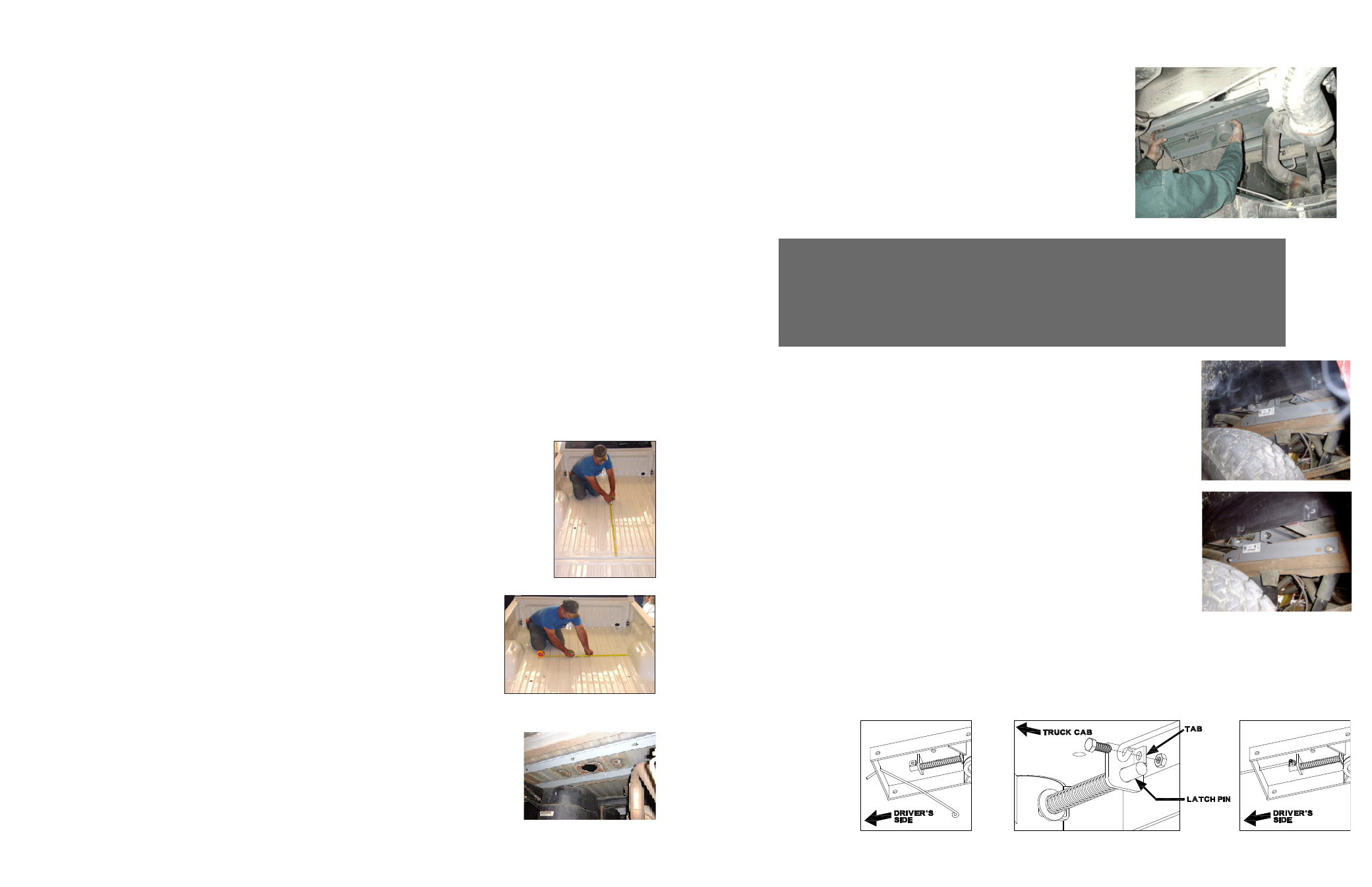
Step 5: INSTALL LATCH PIN RELEASE HANDLE
WARNING: LATCH PIN WILL NOT FUNCTION PROPERLY IF HANDLE IS NOT INSTALLED CORRECTLY.
Install the handle from underneath the truck by inserting it through the slot in the end of the center section toward
the driver’s side rear tire as shown. Attach the handle to the latch pin as shown with the handle on the “cab side”
of the square tab welded to the pin. The head of the bolt must be on the handle side, and the lock nut must be on
the tab side. The tab is welded to the pin in an offset position so that the handle will be lined up over the center
of the pin. If the handle is
fastened to the other side
of the tab, the handle
will not function properly.
When installed correctly
the latch pin may be dis-
engaged from the ball by
pulling on the handle from
the driver’s side wheel well
and rotating the handle
clockwise.