Pressure, Accessories, Application/wiring diagram dimensional drawing – Veris Industries PW2 SERIES Datasheet User Manual
Page 2: Ordering information
pressure
800.354.8556
+1 503.598.4564
www.veris.com
DIGITAL CONTROL
Digital Output
4-20mA IN
POWER SOURCE
12 to 24 VDC
Port Swap/Norm
Bi-Dr/Normal
Slow Avg/Fast Norm
Analog Rev/Norm
Bar/PSI
ZERO
A-High
B-Mid High
C-Mid Low
D-Low
REMOTE
ZERO
4-20mA
Pressure
Range
Settings
Polarity
Insensitive
Default Settings in bold.
Insert jumper to activate
other features.
Model
PW2-03
PW2-04
PW2-05
A
50
100
250
B
25
50
125
C
10
20
50
D
5
10
25
Model
PW2-03
PW2-04
PW2-05
A
3.45
6.89
17.24
B
1.72
3.45
8.62
C
0.69
1.38
3.45
D
0.34
0.69
1.72
Range (psi)
Range (bar)
1
Select operational range according to maximum gauge pressure, NOT differential pressure.
Example: High gauge pressure=90 psig, Select 100 psig model (04).
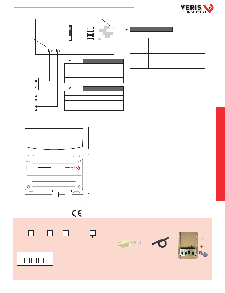
ACCESSORIES
Bypass Valve assemblies (AA14A)
PW installed on bypass valve manifold (AA16A)
Snubbers (AA11, AA12), steam siphon (AA13)
APPLICATION/WIRING DIAGRAM
DIMENSIONAL DRAWING
Local Display
L = LCD Display
X = No Display
NIST
N = NIST
X = None
US or EU
S = Standard
C = CE
Operational Range
1
03 = 0-50 psi/3.45 bar
04 = 0-100 psi/6.89 bar
05 = 0-250 psi/17.24 bar
PW2
Example:
PW2 L X 04 C
Available
ORDERING INFORMATION
HI PORT
100 psi
100 psi
50 psi
50 psi
0 psi
LO PORT
0 psi
50 psi
50 psi
100 psi
100 psi
4-20mA
+100 psi
+50 psi
0 psi
-50 psi
-100 psi
Bidirectional Operation
Input Conditions
Result
Outputs Read
DP
20mA
16mA
12mA
8mA
4mA
2.2"
(57 mm)
4"
(102 mm)
5.8"
(147 mm)
LOW
HIGH
WET DIFFERENTIAL PRESSURE
AA14A
AA13
AA11
HQ0001832.B 01131