Veris Industries H701 Install User Manual
Solid-core current switch, adjustable trip point, Installation guide, Wiring example
6%2)3
CURRENT MONITORING
INSTALLATION GUIDE
Z201482-0D
PAGE 1
©2009 Veris Industries USA 800.354.8556 or +1(0)503.598.4564 / [email protected]
08092
Alta Labs, Enercept, Enspector, Hawkeye, Trustat, Veris, and the Veris ‘V’ logo are trademarks or registered trademarks of Veris Industries, L.L.C. in the USA and/or other countries.
Solid-Core Current Switch,
Adjustable Trip Point
Installer’s Specifications
Sensor Power
Induced from monitored conductor
Insulation Class
600VAC RMS (UL), 300VAC RMS (CE)
Frequency Range
50/60 Hz
Temperature Range
-15° to 60°C (5° to 140°F)
Humidity Range
10-90% RH, non-condensing
Hysteresis
10% (typical)
Terminal Block Maximum Wire Size
14 AWG (16 AWG for H308)
Terminal Block Torque (nominal)
4 in-lbs (7 in-lbs for H308)
Agency Approvals
UL 508 open device listing
CE: EN61010-1:2001-02, CAT III, deg. 2, basic insulation
Do not use the LED status indicators as evidence of applied voltage.
For applications requiring double or reinforced insulation, please contact the factory.
The product design provides for basic insulation only.
)";"3%0'&-&$53*$4)0$, &91-04*0/ 03"3$'-"4)
t 'PMMPXTBGFFMFDUSJDBMXPSLQSBDUJDFT
4FF/'1"&JOUIF64" PSBQQMJDBCMFMPDBMDPEFT
t 5IJTFRVJQNFOUNVTUPOMZCFJOTUBMMFEBOETFSWJDFECZRVBMJmFEFMFDUSJDBMQFSTPOOFM
t 3FBE
VOEFSTUBOEBOEGPMMPXUIFJOTUSVDUJPOTCFGPSFJOTUBMMJOHUIJTQSPEVDU
t 5VSOPõBMMQPXFSTVQQMZJOHFRVJQNFOUCFGPSFXPSLJOHPOPSJOTJEFUIFFRVJQNFOU
t 6TFBQSPQFSMZSBUFEWPMUBHFTFOTJOHEFWJDFUPDPOmSNQPXFSJTPõ
%0/05%&1&/%0/5)*4130%6$5'0370-5"(&*/%*$"5*0/
t 0OMZJOTUBMMUIJTQSPEVDUPOJOTVMBUFEDPOEVDUPST
'BJMVSFUPGPMMPXUIFTFJOTUSVDUJPOTXJMMSFTVMUJOEFBUIPSTFSJPVTJOKVSZ
%"/(&3
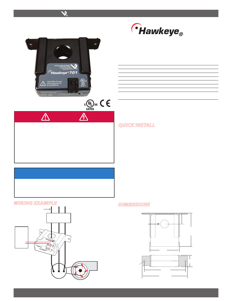
Wiring ExamplE
H701
701
DimEnsions
/05*$&
t 5IJTQSPEVDUJTOPUJOUFOEFEGPSMJGFPSTBGFUZBQQMJDBUJPOT
t %POPUJOTUBMMUIJTQSPEVDUJOIB[BSEPVTPSDMBTTJmFEMPDBUJPOT
t 5IFJOTUBMMFSJTSFTQPOTJCMFGPSDPOGPSNBODFUPBMMBQQMJDBCMFDPEFT
t .PVOUUIJTQSPEVDUJOTJEFBTVJUBCMFmSFBOEFMFDUSJDBMFODMPTVSF
quick install
Disconnect and lock out power.
1.
Install the mounting bracket to the back of the electrical enclosure, no closer than
2.
1/2” (12mm) to an uninsulated conductor.
Slide the conductor to be monitored through the sensing hole of the current
3.
switch. Terminate the conductor. See Notes (page 2) for currents under 1 Amp or
above 135 Amps.
Wire the output connections to the DDC controller or switched load. Note:
4.
Contacts are solid state and work like dry contacts. When the switch is closed, less
than 1 Ω is present. When the switch is open, more than 1 MΩ are present.
Reconnect power.
5.
Calibrate the sensor (see Calibration section).
6.
Fan or Pump
CONTACTOR
DDC CONTROLLER
Insulated Conductor Only
DI
Motor
701
0.2” x 0.15”
slot (2x)
1.1"
(27 mm)
2.8"
(68 mm)
0.7" Dia
(19 mm)
0.9"
(23 mm)
3.0"
(75 mm)
Removable/Adjustable Mounting Bracket
3.8"
(95 mm)
4.2"
(106 mm)