Caution, Installation guide, Operation – Veris Industries H909 Install User Manual
Page 2: Calibration, H909, For load currents less than sensor minimum rating
Z201495-0C
PAGE 2
©2011 Veris Industries USA 800.354.8556 or +1.503.598.4564 / [email protected]
08114
Alta Labs, Enercept, Enspector, Hawkeye, Trustat, Veris, and the Veris ‘V’ logo are trademarks or registered trademarks of Veris Industries, L.L.C. in the USA and/or other countries.
TM
INSTALLATION GUIDE
H909
OPERATION
The H909 is a current-sensitive switching device that monitors current (amperage) in
the conductor passing through it. A change in amperage in the monitored conductor
that crosses the switch (setpoint) threshold plus the hysteresis value will cause
the resistance of the FET status output to change state, similar to the action of a
mechanical switch. In this model, the setpoint is adjustable through the action of a
twenty (20) turn potentiometer (see the CALIBRATION section). The status output is
suitable for connection to building controllers or other appropriate data acquisition
equipment operating at up to 120 volts. The H909 requires no external power supply
to generate its output.
The H909 housing offers unprecedented mounting flexibility. The mounting bracket
can be attached in three different places. Additionally, the bracket is compatible with
the Veris AH01 DIN Rail clip, allowing DIN mounting.
NOTES
TROUBLESHOOTING
For load currents less than sensor minimum rating:
Wrap the monitored conductor through the center hole and around the sensor body
to produce multiple turns through the center window. This increases the current
measured by the transducer.
4x
1A
DANGER: 5A CTs can present hazardous voltages.
Install CTs in accordance with manufacturer's instructions.
Terminate the CT secondary before applying current.
H68xx-5A CT
240A
300A:
5A
4A
> 135A (sensor max.)
For load currents greater than sensor maximum rating:
Use a 5 Amp (H68xx series) Current Transformer (CT) as shown. This technique can be
combined with wrapping (see below) when added safety is desired for a low current
load on a high current source.
Problem
Solution
No Reading at Controller
• Check sensor calibration (see above)
• Check for control voltage at sensor (<120V)
• Check for amperage in monitored conductor (> 2.5A)
• Assure that sensor core mating surfaces are clean and
that the core clamp is completely closed
Setpoint screw has no stops
The setpoint screw has a slip-clutch at both ends of its
travel to avoid damage. Twenty turns CCW will reset
the sensor to be most sensitive. Repeat calibration
above.
Both LEDs are lit
Setpoint screw is too far clockwise. See solution above.
CAUTION
RISK OF EQUIPMENT DAMAGE
• Derate the product’s maximum current for the number of turns
through the sensing window using the following formula.
Rated Max. Amps ÷ Number of Turns = Max. monitored Amps
e.g. : 100A ÷ 4 Turns = 25 Amps max. in monitored conductor
• Failure to follow these instructions can result in overheating
and permanent equipment damage.
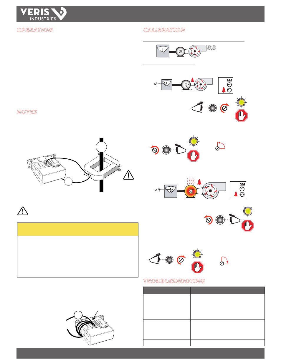
CALIBRATION
A. To monitor under-current (belt loss, coupling shear, status)
A
OK!
!
1. Turn setpoint screw
clockwise until Status OPEN
LED turns ON.
2. Slowly turn the screw counter-clockwise until the Status CLOSED LED just
turns ON.
3.Turn the screw an
additional 1/4 turn
counter-clockwise for
operational margin.
B. To monitor over-current (mechanical problems, seized impeller)
A
OK!
!
3. Turn the setpoint
screw an additional
1/4 turn clockwise for
operational margin.
1.Turn setpoint screw
counter-clockwise until Status
CLOSED LED turns ON.
2. Slowly turn the setpoint screw clockwise until the Status OPEN LED just turns ON.
OK!
STATUS
OK!
STATUS
Setpoint
Status
Open
STOP
Setpoint
Status
Closed
STOP
1/4
Setpoint
+
Setpoint
Status
Closed
STOP
Setpoint
Status
Open
STOP
+
1/4
Setpoint
Before beginning calibration, establish normal load conditions.
OK!
A
OK!
Then choose either A or B below.
Program controller to account
for the extra turns. e.g., if four
turns pass through the sensor
(as shown) divide the normal
controller reading by 4.
< 2.5 A (Sensor Min.)