Installation guide, Installation, Configuration – Veris Industries NWGWA2 Install User Manual
Page 2: Control system power supply nwgwa2
TM
NWGWA2
INSTALLATION GUIDE
Z206321-0B
PAGE 2
©2012 Veris Industries USA 800.354.8556 or +1.503.598.4564 / [email protected]
12121
Alta Labs, Enercept, Enspector, Hawkeye, Trustat, Aerospond, Veris, and the Veris ‘V’ logo are trademarks or registered trademarks of Veris Industries, L.L.C. in the USA and/or other countries.
INSTALLATION
1. Locate the DIN rail clips on the underside of the housing. Snap these clips onto the
DIN rail.
Snap these onto
DIN rail first
Snap this onto
DIN rail when
the first two are
in place
2. To prevent horizontal shifting across the DIN rail, use two Veris AV02 end stop clips.
3. If wall mounting, screw the antenna onto the brass connector. If mounting in a
metal panel, then use a Veris AWB02 antenna extension cable to run between the
brass connector on the NWGWA2 and the panel’s inner antenna connector. Then
screw the antenna into the panel’s outer connector.
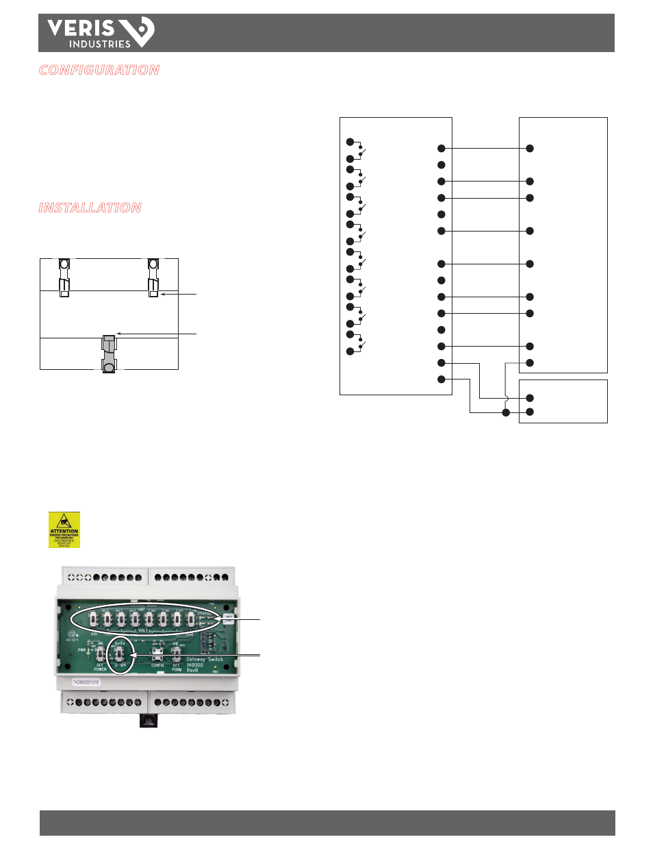
4. Remove the cover and adjust the slide switches to select either V or mA for each
analog output. If using V output, adjust the lower switch to choose either the 0-5V
or the 0-10V range. Replace the cover.
Observe precautions for handling static sensitive
devices to avoid damage to the circuitry that
is not covered under the factory warranty.
Leave the PRGM switch in the off position. The configuration button, the RS-232 port,
and the power switch are described in the Wireless Software Configuration Guide.
Output Slide Switches
(V or mA)
Voltage Range
Selection Switch
CONFIGURATION
Before installing the NWGWA2, it is necessary to configure it for operation. Use a
computer equipped with a USB port and the Veris configuration software, available
from the Veris website, www.veris.com. Configure and map all devices in the wireless
network. See the Veris Wireless Software Configuration Guide for instructions.
When all devices are mapped and configured in the network, proceed to the next
section to mount the NWGWA2.
5. Wire the NWGWA2 analog and digital outputs to the input cards for the building
control system.
+
–
Analog Input
Analog Input
Analog Input
Analog Input
Analog Input
Analog Input
Analog Input
Analog Input
Common
AO1
G
AO2
AO3
G
AO4
AO5
G
AO6
AO7
G
AO8
Pwr +
Pwr –
Control System
Power
Supply
NWGWA2
DO1
DO2
DO3
DO4
DO5
DO6
DO7
DO8
Grounding terminals (G) are supplied on the analog side. Ground as appropriate for the
application and control system used.
6. Replace any terminal block covers that may have been dislodged during wiring.