Veris Industries AA47 Install User Manual
Aa47, Danger, Line switching power pack
ZL0033-0B
PAGE 1
©2012 Veris Industries USA 800.354.8556 or +1.503.598.4564 / [email protected]
03121
Alta Labs, Enercept, Enspector, Hawkeye, Trustat, Veris, and the Veris ‘V’ logo are trademarks or registered trademarks of Veris Industries, L.L.C. in the USA and/or other countries.
TM
OCCUPANCY SENSORS
INSTALLATION GUIDE
Line Switching Power Pack
Installer’s Specifications
Storage Temperature
-29° to 65°C (-20° to 150°F )
Operating Temperature
0° to 40°C (32° to 104°F)
Maximum Humidity
90% RH non-condensing
AC Power Input
120/277 VAC ± 10%, 60 Hz
Output Voltage
24 VDC
Output Current
100 mA max.
Relay Contacts:
Horsepower Rating
1 HP@120V
Switching Capacity
120 VAC, 60 Hz; 15 A tungsten 1800 W
277 VAC, 60 Hz 20 A Ballast
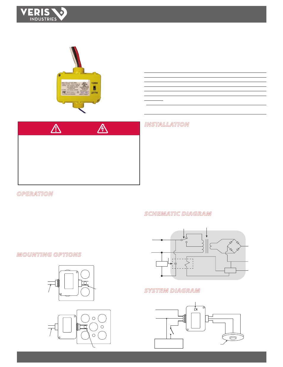
AA47
AA47
OPERATION
The AA47 Line-Switching Power Pack provides local switching capability to control
loads based on the signal from MSC Series occupancy sensors, independently of any
connection to building control systems. The AA47 routes 120/277 VAC, 60 Hz line
power directly to a Form A relay contact (SPST, normally open) to control a load,
and it generates full-wave, 24 VDC to power up to four MSC sensors (depending on
model). The relay is rated for maximum 15 A tungsten and 20 A ballast loads.
Mounted the AA47 either inside or outside a standard junction box using a 1/2-in.,
threaded EMT nipple. Route power to the sensor(s) using plenum-rated cable.
INSTALLATION
1. Provide separate overcurrent protection in accordance with the National Electrical
Code® and applicable local codes.
2. Use copper wire only.
3. Confirm that the device rating is appropriate for your application.
4. Set the voltage selector on the front of the unit to either 120 or 277 V, depending
on your application. The unit is shipped with the selector set to 277 V.
5. Mount the power pack to a suitable junction box using the 1/2-in., threaded nipple
and lock. The power pack is plenum-rated, and can be mounted to the inside or
the outside of a junction box or fixture in a ceiling plenum.
6. Connect the power pack as shown. Use approved wire nuts for electrical
connections.
120V
277V
RED
Load
Ext. Override OFF
RED
BLK
BLK
White
Neutral
Hot
BLUE
Control Input
Common
+24VDC
Voltage Selector
Sensor
Line Voltage
120/277VAC
From Sensor Output
Line Voltage
INSIDE
From Sensor Output
Line Voltage
OUTSIDE
HAZARD OF ELECTRIC SHOCK, EXPLOSION, OR ARC FLASH
• Follow safe electrical work practices.
See NFPA 70E in the USA, or applicable local codes.
• This equipment must only be installed and serviced by qualified electrical personnel.
• Read, understand and follow the instructions before installing this product.
• Turn off all power supplying equipment before working on or inside the equipment.
• Use a properly rated voltage sensing device to confirm power is off.
DO NOT DEPEND ON THIS PRODUCT FOR VOLTAGE INDICATION
Failure to follow these instructions will result in death or serious injury.
DANGER
SCHEMATIC DIAGRAM
SYSTEM DIAGRAM
Hot
Voltage
Selector
Transformer
Red
(+24 VDC)
Black
(Common)
Blue
(Control)
Control
Load
Red
Relay
Neutral
White
Line Voltage
120/277 VAC
Black
MOUNTING OPTIONS