Installation guide, Installation, Wiring – Veris Industries MSC SERIES Install User Manual
Page 2: Dimensions, Msc series, Mounting with supplied mounting post, Mounting to a junction box, Flush mounting
ZL0030-0C
PAGE 2
©2012 Veris Industries USA 800.354.8556 or +1.503.598.4564 / [email protected]
02121
Alta Labs, Enercept, Enspector, Hawkeye, Trustat, Veris, and the Veris ‘V’ logo are trademarks or registered trademarks of Veris Industries, L.L.C. in the USA and/or other countries.
TM
MSC SERIES
INSTALLATION GUIDE
INSTALLATION
Choose a location at least five feet from air flow sources (HVAC vents, fans, etc.). Three
mounting options are available.
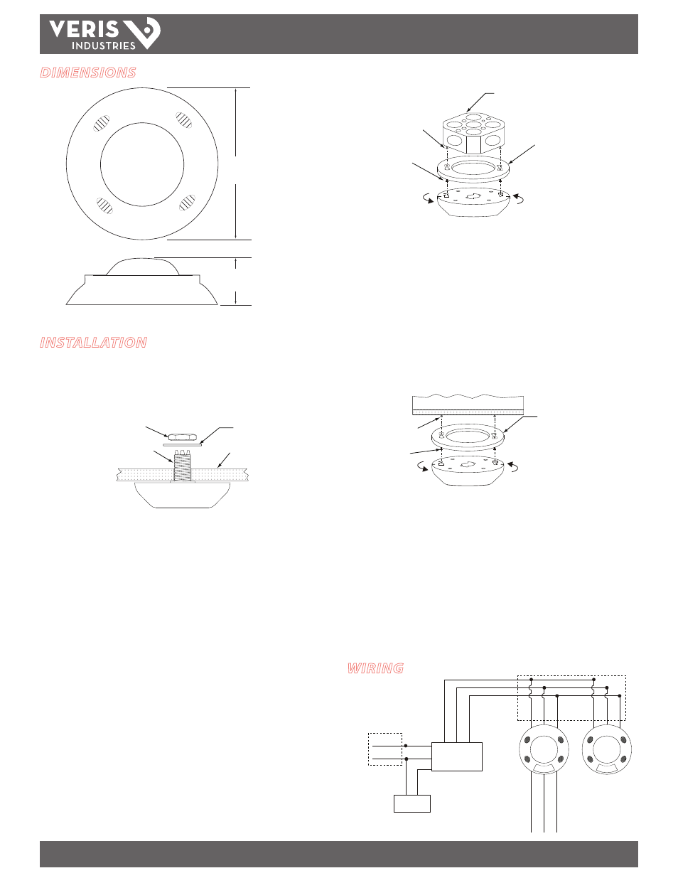
Mounting with Supplied Mounting Post
Washer
Ceiling tile
Lock Nut
Mounting post
1. Turn off the circuit breaker supplying power to the sensor’s power pack.
2. Drill a 7/8” diameter hole at the mounting location. Note: For acoustical tile, use
the threaded mounting post to drill the mounting hole. Press the cutter end of the
post firmly against the tile and twist the post into the tile.
3. Feed sensor wire through the mounting post, then twist and lock the mounting
post to the back of the sensor.
4. Insert the mounting post into the hole drilled in step 2. Secure the sensor
assembly away from the top of the ceiling tile using the supplied washer and lock
nut.
5. Wire the sensor (see Wiring section). Follow applicable national and local electrical
codes.
Mounting to a Junction Box
Junction Box
Mounting Adapter Plate
Rotate Clockwise
Keyhole Pin
#8 x 32 screw
1. Turn off the circuit breaker supplying power to the sensor’s power pack.
2. Attach the adapter plate to a standard 4-in. ceiling junction box using the two #8 x
32 screws supplied.
3. Wire the sensor (see Wiring section). Follow applicable national and local electrical
codes.
4. Attach the sensor to the adapter plate by inserting the pins on the adapter plate
into the keyholes on the back of the sensor. Rotate the sensor clockwise until it
locks in place.
Flush Mounting
Mounting Adapter Plate
Rotate Clockwise
Ceiling
Mounting Screw
Keyhole Pin
1. Turn off the circuit breaker supplying power to the sensor’s power pack.
2. Drill a hole large enough to accomodate wiring at the mounting location.
3. Attach the adapter plate to the ceiling using a secure method, such as with screws
and wall anchors (not provided).
4. Wire the sensor (see Wiring section). Follow applicable national and local electrical
codes.
5. Attach the sensor to the adapter plate by inserting the pins on the adapter plate
into the keyholes on the back of the sensor. Rotate the sensor until it locks in
place.
WIRING
Contact rating:
1A @ 24 Vdc Resistive
Hot
Neutral
Black
White
Red
Black
Blue
R
e
d
Black
Blue
R
ed
Black
Blue
R
ed
Orange (N.O
.)
Y
el
lo
w
(C
ommon)
Green (N.C.)
Power Pack
AA47
Load
Class 1
Class 2
Additional
Sensor(s)
(optional)
DIMENSIONS
4.6”
(117mm)
MSCU: 1.4” (36mm)
MSCD/MSCP: 1.8” (46mm)