Caution, Installation guide, Wiring diagram digital control – Veris Industries H970HCB Install User Manual
Page 2: Operation, Set-up and wiring, Scaling, Troubleshooting, H970hcb, For load currents less than sensor minimum rating, Sensor output
6%2)3
INSTALLATION GUIDE
H970HCB
Z203257-0D
PAGE 2
©2009 Veris Industries USA 800.354.8556 or +1(0)503.598.4564 / [email protected]
07091
Alta Labs, Enercept, Enspector, Hawkeye, Trustat, Veris, and the Veris ‘V’ logo are trademarks or registered trademarks of Veris Industries, L.L.C. in the USA and/or other countries.
opEration
The H970HCB is a current-sensitive device that monitors DC current (amperage)
in the conductor passing through it. The unit combines a Hall Effect sensor with
proven transducer circuitry, with a status output suitable for connection to building
controllers or other appropriate data acquisition equipment operating at up to
30 volts. The H970HCB requires 15-30VAC/DC to generate its output. Selectable
amperage ranges and output types maximize the installation flexibility.
The H970HCB housing offers unprecedented mounting flexibility. The mounting
bracket can be attached in three different places. Additionally, the bracket is
compatible with the Veris AH01 DIN Rail clip, allowing DIN mounting.
notEs
For load currents less than sensor minimum rating:
Wrap the monitored conductor through the center hole and around the sensor body
to produce multiple turns through the “window.” This increases the current measured
by the transducer.
Controller must be programmed to account for
the extra turns. e.g., if four turns pass through
the sensor (as shown) the normal controller
reading must be divided by 4.
CAUTION
RISK OF EQUIPMENT DAMAGE
t %FSBUFUIFQSPEVDUTNBYJNVNDVSSFOUGPSUIFOVNCFSPGUVSOT
UISPVHIUIFTFOTJOHXJOEPXVTJOHUIFGPMMPXJOHGPSNVMB
3BUFE.BY"NQT/VNCFSPG5VSOT.BYNPOJUPSFE"NQT
FH"5VSOT"NQTNBYJONPOJUPSFEDPOEVDUPS
t 'BJMVSFUPGPMMPXUIFTFJOTUSVDUJPOTDBOSFTVMUJOPWFSIFBUJOH
BOEQFSNBOFOUFRVJQNFOUEBNBHF
4x
1A
< 3.5 A (Sensor Min.)
Failure to observe the following can result in distorted product calibration:
Observe the arrow on the product showing orientation to current source.
1.
Do not expose the product to current levels greater than the maximum amperage
2.
range.
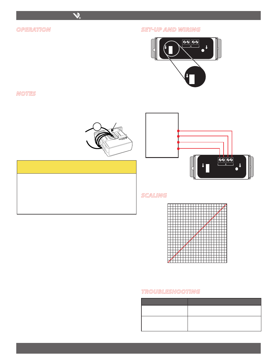
sEt-up anD Wiring
Slide Switch
Amp Ranges
0-50
0-100
0-200
Amperage Range
Selector Switch
Amp Ranges
0-50
0-100
0-200
To
Load
To
Load
4-20
mA
0-10
VDC
Gnd Power
15-24 VAC/DC
Blink=Normal
Off=No Power
Solid=Overrange
Wiring Diagram
Digital Control
(+) Power
(-) GND
0-10 VDC
4-20mA
AI
Amp Ranges
0-50
0-100
0-200
To
Load
To
Load
4-20
mA
0-10
VDC
Gnd Power
15-24 VAC/DC
Blink=Normal
Off=No Power
Solid=Overrange
scaling
SENSED AMPS
50/100/200A*
4mA/0VDC
0A
20mA/5/10VDC
SENSOR OUTPUT
*Slide-Switch Selectable
SENSED AMPS
20/40/80A*
4mA/0VDC
0A
20mA/5/10VDC
SENSOR OUTPUT
*Slide-Switch Selectable
troublEshooting
Problem
Solution
The LED is off and no signal is
produced
Verify that power is applied to PWR (+) and GND (-)
terminals
The LED is on solid and the output
is at maximum
Verify that the amperage range selection switch is
in the proper position for the current applied to the
conductor.