Fl ow, Dimensional drawings ordering information, Model manuf. part # description – Veris Industries 3x0 SERIES Datasheet User Manual
Page 2: Other models available
fl
ow
800.354.8556
+1 503.598.4564
www.veris.com
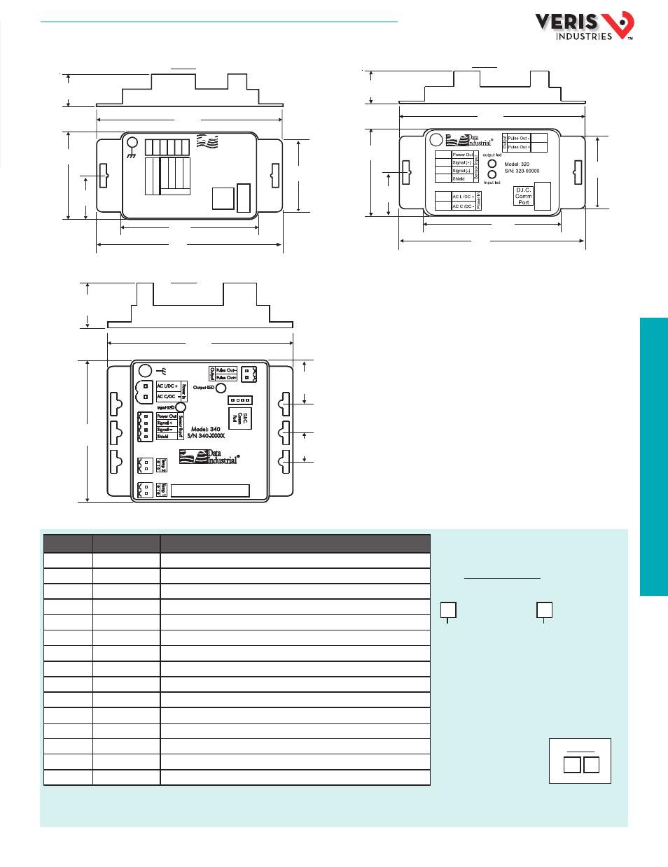
DIMENSIONAL DRAWINGS
ORDERING INFORMATION
310-00
MODEL
MANUF. PART #
DESCRIPTION
U001-0013
310-00*
Flow Transmitter, Analog, Programmable, 4-20mA output
U001-0027
340LW-00*
Flow Transmitter, BTU, Analog, Programmable, LonWorks output
U001-0029
340N2-00**
Flow Transmitter, BTU, Analog, Programmable, N2 output
U001-0035
310-04*
Flow Transmitter, Analog, 4-20mA, DIN mounting
U001-0038
340N2-02**
Flow Transmitter, BTU, Analog, Programmable, N2 output, metal enclosure
U001-0042
310-01*
Flow Transmitter, Analog, 4-20mA, NEMA 4X enclosure
U001-0136
340BN/MB-00*
,
*** Flow Transmitter, BTU, BN-MB, No enclosure
U001-0137
340BN/MB-02*
,
*** Flow Transmitter, BTU, BN-MB, Metal Enclosure
U001-0138
340BN/MB-03*
,
*** Flow Transmitter, BTU, BN-MB, Plastic Enclosure
U001-0139
340BN/MB-04*
,
*** Flow Transmitter, BTU, BN-MB, with DIN Clips
U001-0060
320-00*
Flow Transmitter, Programmable, Scaled pulse output
U001-0109
340-00*
,
***
Flow Transmitter, Programmable, frequency output
U001-0020
A301-20
Programming cable with CD for analog/Modbus/BACnet/LonWorks outputs, serial PC connector
U001-0075
A302-20
Programming cable with CD for N2 output, serial PC connector
U001-0149
40134-0002
Programming cable with CD for analog/Modbus/BACnet/LonWorks outputs, USB PC connector
320-00
340-00
Model
310 = Analog
320 = Pulse
340 = BTU
340N2 = BTU; N2 protocol
340BN/MB = BTU; Bacnet and
Modbus protocol
340LW = BTU; LonWorks
Options
00 = Transmitter only
01 = NEMA 4 enclosure
(310, 320 only)
02 = Metal weathertight
enclosure
03 = Plastic weathertight
enclosure
04 = DIN rail mounting clips
Other models available:
* Software and programming cable are required for analog, Modbus, LonWorks, BACnet transmitter and meter products.
** Software and programming cable required for N2 products.
*** 340 Series also requires two 10k Dale thermistors for energy (BTU) measurement.
S/ N: 310-00000
Sensor Inputs
Side
4-
20
m
A
Lo
op
(-)
4-
20
m
A
Lo
op
(+
)
S
hi
el
d
G
ro
un
d
Po
w
er
(4
00
0
on
ly
)
Model: 310
Programmable
Analog
Transmitter
D.I.C.
Comm
Port
S
ig
nal
(-
)
S
ig
nal
(+
)
Mattapoisett, MA 02739
®
Data
Industrial
1.5”
(39 mm)
0.9”
(23 mm)
3.25”
(83 mm)
1.5”
(39 mm)
3.7”
(94 mm)
1.75”
(45 mm)
2.75”
(70 mm)
Side
1.5”
(39 mm)
1.5”
(39 mm)
3.7”
(94 mm)
1.75”
(45 mm)
0.9”
(23 mm)
3.25”
(83 mm)
2.75”
(70 mm)
Side
1.6”
(40 mm)
0.9”
(23 mm)
0.6”
(15 mm)
3.7”
(94 mm)
3.0”
(75 mm)
Example:
340 02
HQ0001785.D 01131