Caution, Typical coil performance, Relay contact ratings – Veris Industries H930 Install User Manual
Page 2: Installation guide, Operation, Troubleshooting, Relay information, Relay load
6%2)3
INSTALLATION GUIDE
H930
Z201496-0B
PAGE 2
©2009 Veris Industries USA 800.354.8556 or +1(0)503.598.4564 / [email protected]
06091
Alta Labs, Enercept, Enspector, Hawkeye, Trustat, Veris, and the Veris ‘V’ logo are trademarks or registered trademarks of Veris Industries, L.L.C. in the USA and/or other countries.
opEration
The H930 is a current-sensitive switching device that monitors current (amperage) in
the conductor passing through it. A change in amperage in the monitored conductor
that crosses the switch (setpoint) threshold plus the hysteresis value will cause
the resistance of the FET status output to change state, similar to the action of a
mechanical switch. This model is equipped with a command relay. The status output
is suitable for connection to building controllers or other appropriate data acquisition
equipment operating at up to 30 volts. The H930 requires no external power supply
to generate its output.
The H930 housing offers unprecedented mounting flexibility. The mounting bracket
can be attached in three different places. Additionally, the bracket is compatible with
the Veris AH01 DIN Rail clip, allowing DIN mounting.
notEs
For load currents less than sensor minimum rating:
Wrap the monitored conductor through the center hole and around the sensor body
to produce multiple turns through the "window." This increases the current measured
by the transducer.
DANGER: 5A CTs can present hazardous voltages.
Install CTs in accordance with manufacturer's instructions.
Terminate the CT secondary before applying current.
H68xx-5A CT
240A
300A:
5A
4A
> 200A (Sensor max.)
For load currents greater than sensor maximum rating:
Use a 5 Amp (H68xx series) Current Transformer (CT) as shown.
troublEshooting
Problem
Solution
No Reading at Controller
• Check that no more than 30VAC/DC or 1.0A has passed
through the contact.
• Check for amperage in monitored conductor (>1.5A)
• Assure that sensor core mating surfaces are clean and
that the core clamp is completely closed
Relay chatters or will not change
state
• Check that not more than 24VAC/DC has been applied
to the relay coil.
• Parallel applications with AC transformers can
damage the relay. Use an appropriate snubbing
device (see www.veris.com/apps/snub.htm for more
information)
CAUTION
RISK OF EQUIPMENT DAMAGE
t %FSBUFUIFQSPEVDUTNBYJNVNDVSSFOUGPSUIFOVNCFSPGUVSOT
UISPVHIUIFTFOTJOHXJOEPXVTJOHUIFGPMMPXJOHGPSNVMB
3BUFE.BY"NQT/VNCFSPG5VSOT.BYNPOJUPSFE"NQT
FH"5VSOT"NQTNBYJONPOJUPSFEDPOEVDUPS
t 'BJMVSFUPGPMMPXUIFTFJOTUSVDUJPOTDBOSFTVMUJOPWFSIFBUJOH
BOEQFSNBOFOUFRVJQNFOUEBNBHF
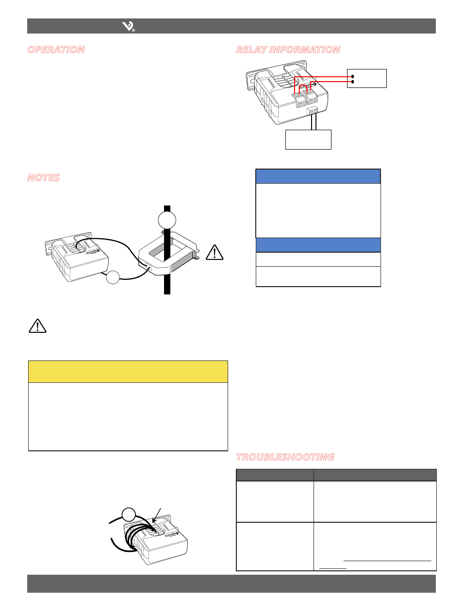
rElay information
Controller must be
programmed to account for the
extra turns. e.g., if four turns
pass through the sensor (as
shown) the normal controller
reading must be divided by 4.
< 1.5 A (Sensor Min.)
RELAY LOAD
Relay Coil
Power Source*
Voltage
AC
DC
24V................................... 10mA
10mA
12V............................................................... 20mA
TYPICAL COIL PERFORMANCE
Hx3x, Hx5x (SPST, N.O.)
Resistive..................................10A@250VAC, 30VDC
Inductive.................................5A@250VAC, 30VDC
RELAY CONTACT RATINGS
Hx4x (SPDT)
Resistive.................................. 8A@250VAC, 30VDC
Inductive................................. 3.5A@250VAC, 30VDC
4x
1A
0.1 A