Veris Industries H10F Install User Manual
H10f, Notice, Danger
TM
CURRENT MONITORING
INSTALLATION GUIDE
Z204651-0F
PAGE 1
©2012 Veris Industries USA 800.354.8556 or +1.503.598.4564 / [email protected]
02121
Alta Labs, Enercept, Enspector, Hawkeye, Trustat, Veris, and the Veris ‘V’ logo are trademarks or registered trademarks of Veris Industries, L.L.C. in the USA and/or other countries.
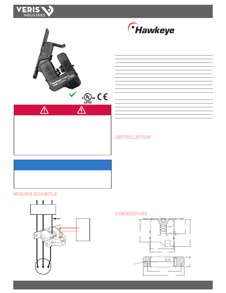
Split-Core Current Switch, Auto Calibration
Installer’s Specifications
Amperage Range
3.5-100 A Continuous
Sensor Supply Voltage
Induced from monitored conductor
Insulation Class
600 VAC RMS (UL); 300 VAC RMS (CE)
Temperature Range -15° to 60°C (5° to 140°F)
Humidity Range
10-90% RH non-condensing
Status Output Ratings
N.O. 1.0A@30VAC/DC not polarity sensitive
On-state Resistance
≤1.0 ohms
Off-state Resistance
≥1 megohm
Frequency Range
50/60 Hz
Setpoint Target Range
±20% window around learned setpoint, nominal@25˚C*
Alarm Reset Range
±15% window around learned setpoint, nominal@25˚C*
Setpoint Calibration Learn Period
Self-learning on 5 sec. pushbutton actuation,
30
sec. learn period
NORMAL-to-ALARM Status Output Delay
1 sec. max.
ALARM-to-NORMAL Status Output Delay
30 sec. nominal**
Terminal Block Max. Wire Size
14 AWG
Terminal Block Torque (nom.)
4 in-lbs (0.45 N-m)
Agency Approvals
UL508, E150462
*For best performance, monitor 5A or greater. At lower currents, these ranges are approximate.
**If current switch experiences a momentary loss of power, 30 second delay may not apply.
Specification Note: For CE compliance, conductor shall be insulated according to IEC 61010-1:2010,
Installation Category III or equivalent. The unit design provides for basic insulation only.
HAZARD OF ELECTRIC SHOCK, EXPLOSION, OR ARC FLASH
• Follow safe electrical work practices.
See NFPA 70E in the USA, or applicable local codes.
• This equipment must only be installed and serviced by qualified electrical personnel.
• Read, understand and follow the instructions before installing this product.
• Turn off all power supplying equipment before working on or inside the equipment.
• Use a properly rated voltage sensing device to confirm power is off.
DO NOT DEPEND ON THIS PRODUCT FOR VOLTAGE INDICATION
• Only install this product on insulated conductors.
Failure to follow these instructions will result in death or serious injury.
DANGER
WIRING EXAMPLE
H10F
TM
10F
DIMENSIONS
NOTICE
• This product is not intended for life or safety applications.
• Do not install this product in hazardous or classified locations.
• The installer is responsible for conformance to all applicable codes.
• Mount this product inside a suitable fire and electrical enclosure.
INSTALLATION
Disconnect and lock out power to the enclosure containing the
conductor to be monitored.
1. Locate a mounting surface for the removable mounting bracket that will allow the
monitored conductor to pass through center window when it is installed and that
will keep the product at least 1/2” from any uninsulated conductors. Determine cable
routing for the controller connection, allowing wiring to reach the mounting location.
2. Drill holes to mount the bracket to the chosen surface using the included screws.
3. Wire the output connections between the sensor and the controller (solid-state
contact).
4. Snap the sensor over the wire to be monitored and clip the assembly to the mounting
bracket.
5. Secure enclosure and reconnect power.
Load
DDC CONTROLLER
Insulated
conductor
only
DI
CONTACTOR
2.5"
(64 mm)
2.0"
(51 mm)
2.1"
(54 mm)
3.5"
(89 mm)
2.9"
(74 mm)
0.4” x 0.2”
(10 mm x 5 mm)
Slot (2x)
1.2"
(31 mm)
Removable Mounting Bracket
0.6"
(16 mm)
0.5"
(13 mm)
2.1"
(54 mm)
1.0"
(26 mm)
RoHS
Compliant