Le ak dete ction, Dimensional drawings application/wiring diagrams, Blink code key ordering information – Veris Industries LDRA6 Datasheet User Manual
Page 2: Model manuf. part # description, Model led indication device status, Rohs
LE
AK DETE
CTION
800.354.8556
+1 503.598.4564
www.veris.com
MODEL
MANUF. PART # DESCRIPTION
U006-0002*
LD300*
Leak Panel, 1 zone, LED, 2 relay outputs
U006-0001** LD1000**
Leak Panel/Remote Annunciator, 1 zone, supervised, relay output
U006-0036** LDRA6**
Leak Panel, up to 6 zones, supervised, relay output, Modbus RTU
U006-0035
LC-KIT
†
Leader cable kit for SC cables (connects from leak panel to SC or NSC cable)
U006-0061
LC-KIT-M
††
Leader cable kit for SC-C and SC-H cables (connects from leak panel to
SC-C or SC-H cable)
U006-0004
FM1114
Reference map, framed (11” x 14”)
U006-0037
WA-DC-05
Power Supply for LD300
* Power supply not included; requires WA-DC-05 power supply.
** Power supply not included; requires Veris PS24-7.5W power supply or equivalent.
†
Included with LD300 and LD1000.
††
Not included with LD300 and LD1000. Required for installation of SC-C ad SC-H cables.
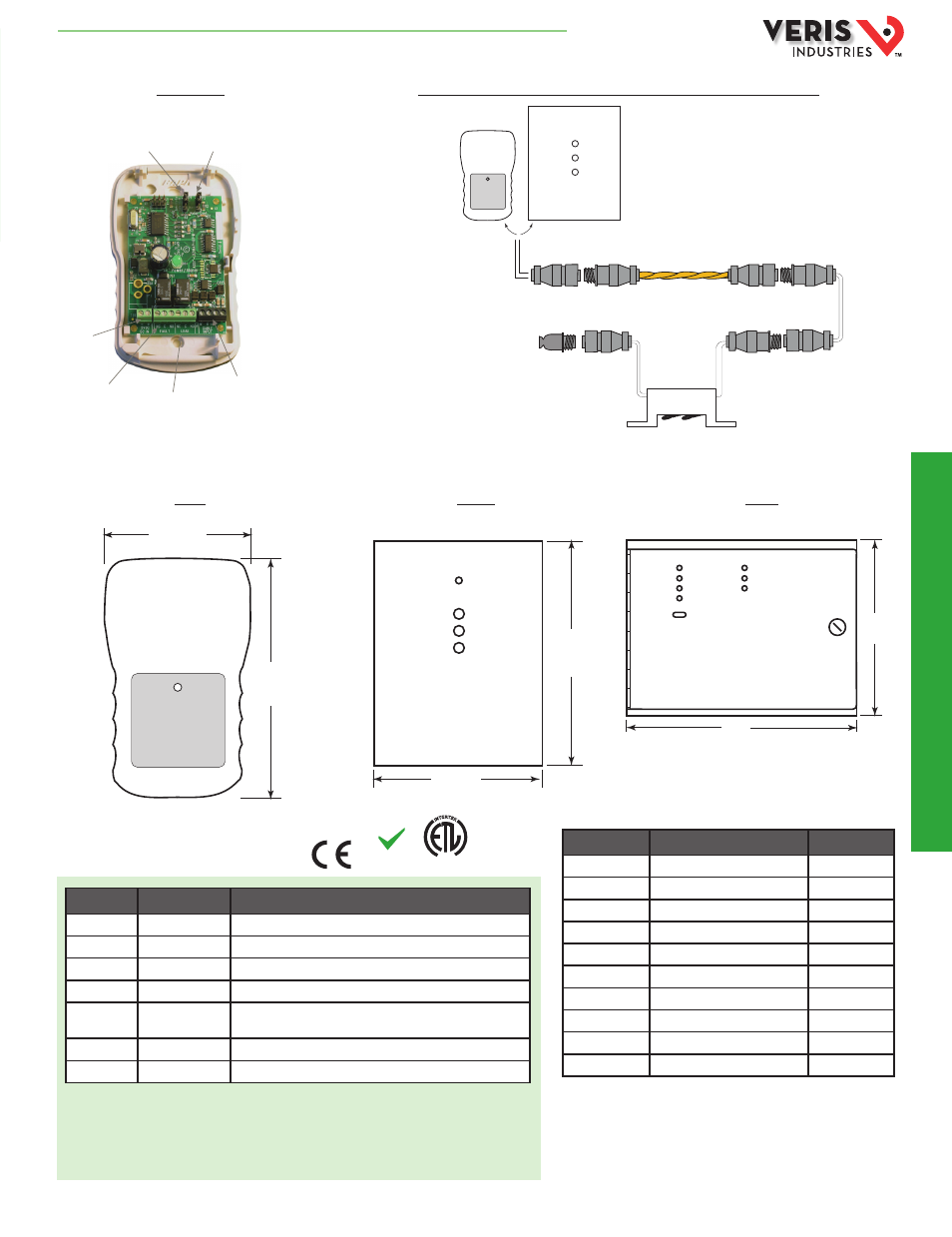
DIMENSIONAL DRAWINGS
APPLICATION/WIRING DIAGRAMS
LD300 or LD1000 basic installation with SC Sensing Cable and SD-Z Spot Detector
LD1000
LDRA6
LD300
LD300 Wiring
Model
LED Indication
Device Status
LD300
Solid green (on or off)
Normal operation
LD300
Flashing green (0.5 sec on/2.5 sec off) Cable fault
LD300
Flashing green (0.5 sec on/0.5 sec off) Leak detected
LD1000
Solid green (on or off)
Normal operation
LD1000
1 amber
Cable fault
LD1000
1 red
Leak detected
LDRA6
Solid green (on or off)
Normal operation
LDRA6
1 green
Power on
LDRA6
1 red
Leak detected
LDRA6
1 yellow
Cable fault
BLINK CODE KEY
ORDERING INFORMATION
RoHS
Compliant
INTE
RTEK
C
US
LISTED
CM
LISTED
3037024
Power/Alarm
LD300
or
SC
NSC
End Terminator
(EOL)
Leader cable kit
(LC-Kit)
Spot detector
(SD-Z)
LD1000
SC Cable Input
White | Black | Green | Red
5VDC Input
Fault Relay Output
N/C | C | N/O
Leak Relay Output
N/C | C | N/O
Leak Sensing Sensitivity
(Top – High, Bottom – Low)
Relay Output Configuration
(Top – Supervised,
Bottom – Non-supervised)
Power/Alarm
2.7”
(69 mm)
4.4”
(112 mm)
Power
Fault
Leak
Quiet/Reset/Test
5.5”
(140 mm)
4.2”
(105 mm)
Alarm/Zone 1
Alarm/Zone 2
Alarm/Zone 3
Power
Alarm/Zone 4
Alarm/Zone 5
Alarm/Zone 6
Test/Reset/Silence
8.0”
(203 mm)
10.5”
(267 mm)
HQ0001795.B 01131