Caution, Installation guide, Operation – Veris Industries H722HC Install User Manual
Page 2: Wiring, Calibration/scaling, H722hc, For load currents less than sensor minimum rating, Amperage range selector switch
6%2)3
INSTALLATION GUIDE
H722HC
Z202942-0A
PAGE 2
©2008 Veris Industries USA 800.354.8556 or 503.598.4564 / [email protected]
09083
Alta Labs, Enercept, Enspector, Hawkeye, Trustat, Veris, and the Veris ‘V’ logo are trademarks or registered trademarks of Veris Industries, L.L.C. in the USA and/or other countries.
300A:
5A
300A
5A
50A
Controller:
CT max ÷ H722HC max
300 ÷ 50 = 6x
300 A
200
100
50
opEration
The H722HC is a current transducer that senses current (amperage) in any of three
field-selectable ranges: 0-50, 0-100, or 0-200 amperes. These ranges represent
the maximum current that can be applied to the monitored conductor. The H722HC
transforms the monitored current into a 0-5VDC output suitable for connection to
building controllers or other appropriate data acquisition equipment. The H722HC
requires no external power to generate its output.
notEs
troublEshooting
For load currents less than sensor minimum rating:
Wrap the monitored conductor through the center hole and around the sensor body
to produce multiple turns through the "window." This increases the current measured
by the transducer.
• Controller must be
programmed to account
for the extra turns. e.g., if
four turns pass through
the sensor (as shown) the
normal controller reading
must be divided by 4.
< 5A (H722HC min.)
4A
4x
50A
Controller: 10A/volt
Amps ÷ Turns
(16A ÷ 4) = 4A
1.6V
(16A)
4A
200
100
50
DANGER: 5A CTs can present hazardous voltages.
Install CTs in accordance with manufacturer's instructions.
Terminate the CT secondary before applying current.
H681x-5A CT
> 200A (H722HC max.)
For load currents greater than sensor maximum rating:
Use a 5 Amp (H681x series) Current Transformer (CT) as shown.
CAUTION
RISK OF EQUIPMENT DAMAGE
• Derate the product’s maximum current for the number of
turns through the sensing window using the following
formula.
Rated Max. Amps ÷ Number of Turns = Max. monitored Amps
e.g. : 30A ÷ 4 Turns = 7.5 Amps max. in monitored conductor
Failure to follow these instructions can result in overheating
and permanent equipment damage.
Problem
Solution
No Reading at Controller
• Confirm measured current is within the selected
range on the product.
• Check polarity of sensor output connections.
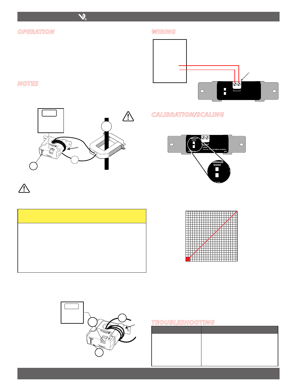
Wiring
Amperage Range
Selector Switch
200
100
50
200
100
50
calibration/scaling
Set the amperage range selector switch to a level appropriate for your load. The
H722HC is available with three choices, 0-50, 0-100, or 0-200 Amps.
SENSED AMPS
Selected Range*
0 VDC
0A
5 VDC
SENSOR OUTPUT
*Factory calibrated ranges selected
with the amperage range switch
DDC
CONTROLLER
AI
COMM
0-5VDC Input
CAUTION: Consult
instructions prior
to installation
!
Use min. 75º C insulated conductor
ig20
AMPERAGE
RANGE
40
20
10
OUTPUT
0-10VDC
+ –
+
–
Self-Powered Output
Scale the output as shown below.
10x