Veris Industries H720 Install User Manual
H720, Notice, Danger
TM
CURRENT MONITORING
INSTALLATION GUIDE
Z201379-0A
PAGE 1
©2012 Veris Industries USA 800.354.8556 or +1.503.598.4564 / [email protected]
01121
Alta Labs, Enercept, Enspector, Hawkeye, Trustat, Veris, and the Veris ‘V’ logo are trademarks or registered trademarks of Veris Industries, L.L.C. in the USA and/or other countries.
Solid-Core Current Sensor, 4-20 mA Output,
VFD Compatible
Installer’s Specifications
Sensor Power
12-30 VDC, 30 mA max.
Amperage Range
0 to 200 A continuous
Insulation Class
600 VAC RMS
Output
4-20 mA
Zero Adjustment
3.5 to 4.5 mA
Span Adjustment
20 to 200 A, full scale
Frequency Range
10 to 80 Hz
Temperature Range -15° to 60°C (5° to 140°F)
Humidity Range
10-90% RH non-condensing
Accuracy
0.5% (combined linearity, hysteresis, and repeatability
Response Time
2 sec
Terminal Block Max. Wire Size
14 AWG
Terminal Block Torque (nom.)
4 in-lbs (0.45 N-m)
Agency Approvals
UL 508, E150462
The product design provides for basic insulation only.
HAZARD OF ELECTRIC SHOCK, EXPLOSION, OR ARC FLASH
• Follow safe electrical work practices.
See NFPA 70E in the USA, or applicable local codes.
• This equipment must only be installed and serviced by qualified electrical personnel.
• Read, understand and follow the instructions before installing this product.
• Turn off all power supplying equipment before working on or inside the equipment.
• Use a properly rated voltage sensing device to confirm power is off.
DO NOT DEPEND ON THIS PRODUCT FOR VOLTAGE INDICATION
• Only install this product on insulated conductors.
Failure to follow these instructions will result in death or serious injury.
DANGER
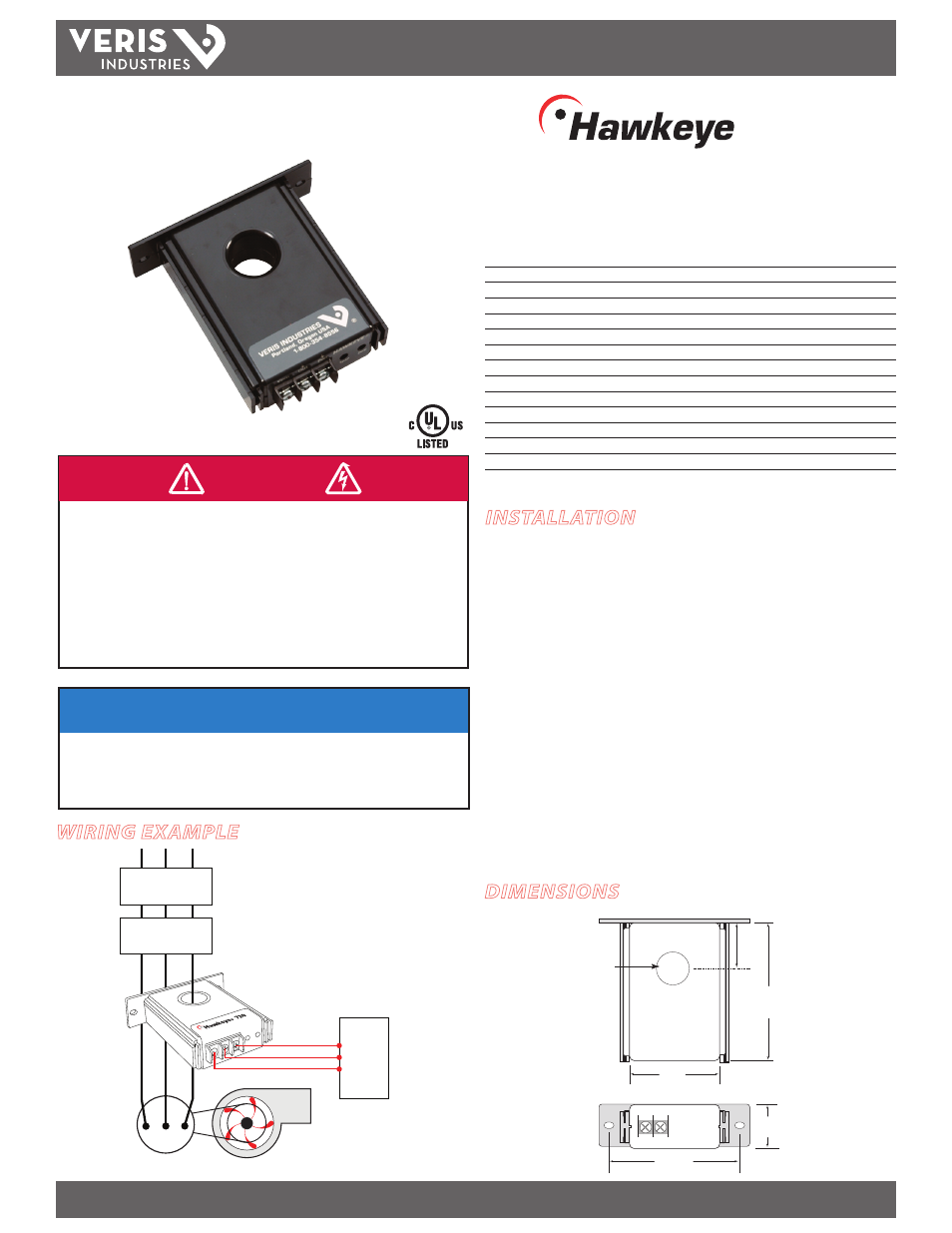
WIRING EXAMPLE
H720
TM
720
DIMENSIONS
NOTICE
• This product is not intended for life or safety applications.
• Do not install this product in hazardous or classified locations.
• The installer is responsible for conformance to all applicable codes.
• Mount this product inside a suitable fire and electrical enclosure.
INSTALLATION
Disconnect and lock out power to the enclosure containing the
conductor to be monitored.
1. Locate a mounting surface for the removable mounting bracket that will allow
the monitored conductor to pass through the center window when it is installed
and that will keep the device at least 1/2” from any uninsulated conductors.
Determine cable routing for the controller connection, allowing wiring to reach
the mounting location.
2. Drill holes to mount the bracket to the chosen surface using the included screws.
3. Wire the output connections between the sensor and the controller (solid-state
contact).
4. Route the conductor through the sensor’s center window and slip the assembly
into the mounting bracket.
5. Adjust the Zero and Span settings. Span can be set at any point from 20A to 200A.
6. Secure enclosure and reconnect power.
0.75" Dia
(19 mm)
3.13"
(80 mm)
0.33"
(9 mm)
2.15"
(55 mm)
3.0"
(76 mm)
1.00"
(26 mm)
0.7" Dia
(19 mm)
Removable/Adjustable Mounting Bracket
Fan or Pump
CONTROLLER
GND
4-20mA IN
12 - 30VDC
Motor
VFD
CONTACTOR
AI