Installation guide, Operation, Installation – Veris Industries AH25 Install User Manual
Page 2: Product diagram, Ah24/ah25, Adapter boards bcm board, Right
6%2)3
inStALLAtion gUiDe
AH24/AH25
Z205211-0B
PAGE 2
©2008 Veris Industries USA 800.354.8556 or 503.598.4564 / [email protected]
10082
Alta Labs, Enercept, Enspector, Hawkeye, Trustat, Veris, and the Veris ‘V’ logo are trademarks or registered trademarks of Veris Industries, L.L.C. in the USA and/or other countries.
oPeration
When an individual current sensor on a strip is damaged, a replacement sensor can by
wired in its place so that the board will continue to operate. The kit includes a pair of
adapter boards (“daughter” boards). Attaching the adapter boards to the BCM board
provides places to plug in the ribbon cable for the sensor strip, as well as to wire as
many individual current sensors as are needed.
The adapter boards are used in conjunction with Veris split-core current sensors, part
number H6806C-0050 or H6806B-0100, sold separately.
Note: The accuracy of the replaced sensed channel will be degraded.
installation
Disconnect and lock out power to the panel.
1.
Remove the ribbon cable from the headers on the BCM board.
2.
Attach the LEFT adapter board to the left header on the BCM; attach the RIGHT
3.
adapter board to the right header.
Use screws (included) to attach the adapter boards to the BCM main board more
4.
securely.
Connect the ribbon cables to the headers on the adapter boards.
5.
Locate the correct terminal block corresponding to the damaged current sensor
6.
on the CT strip. Wire a split core current sensor to this terminal block and snap
the current sensor around the conductor in the panel. Repeat this step for each
damaged current sensor.
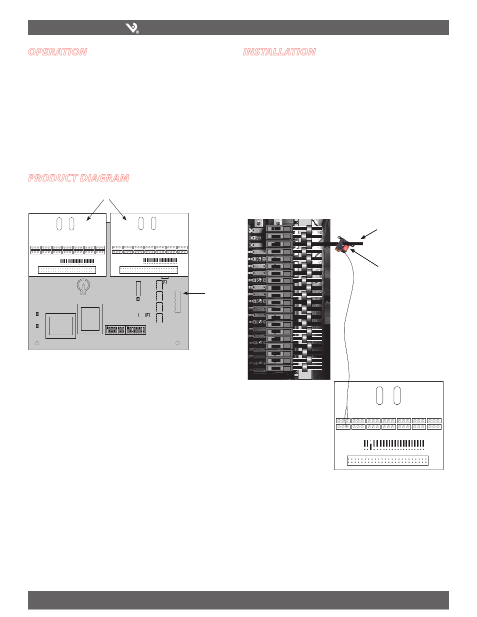
ProDuct Diagram
12
2
3
5
9
LEFT
RIGHT
RX
TX
ALIVE
41
39
37
35
33
31
29
27
25
23
21
19
17
15
13
11
9
7
5
3
1
LEFT
42
40
38
36
34
32
30
28
26
24
22
20
18
16
14
12
10
8
6
4
2
RIGHT
NORMAL
EXT CT
NORMAL
EXT CT
Adapter Boards
BCM board
20
20
20
20
20
20
20
20
20
20
20
20
20
20
20
20
20
20
20
20
42
40
38
36
34
32
30
28
26
24
22
20
18
16
14
12
10
8
6
4
2
RIGHT
NORMAL
EXT CT
Split-core current sensor
(sold separately)
Conductor, connected
to Circuit #6
Change the position of the
7.
jumper corresponding to
the damaged sensor from
NORMAL to EXT CT.
Reconnect power to the panel.
8.