Installation guide, Wiring example – Veris Industries H540NS Install User Manual
Page 4
Z202763-0D
PAGE 4
©2012 Veris Industries USA 800.354.8556 or +1.503.598.4564 / [email protected]
07122
Alta Labs, Enercept, Enspector, Hawkeye, Trustat, Veris, and the Veris ‘V’ logo are trademarks or registered trademarks of Veris Industries, L.L.C. in the USA and/or other countries.
TM
INSTALLATION GUIDE
H540NS/548NS
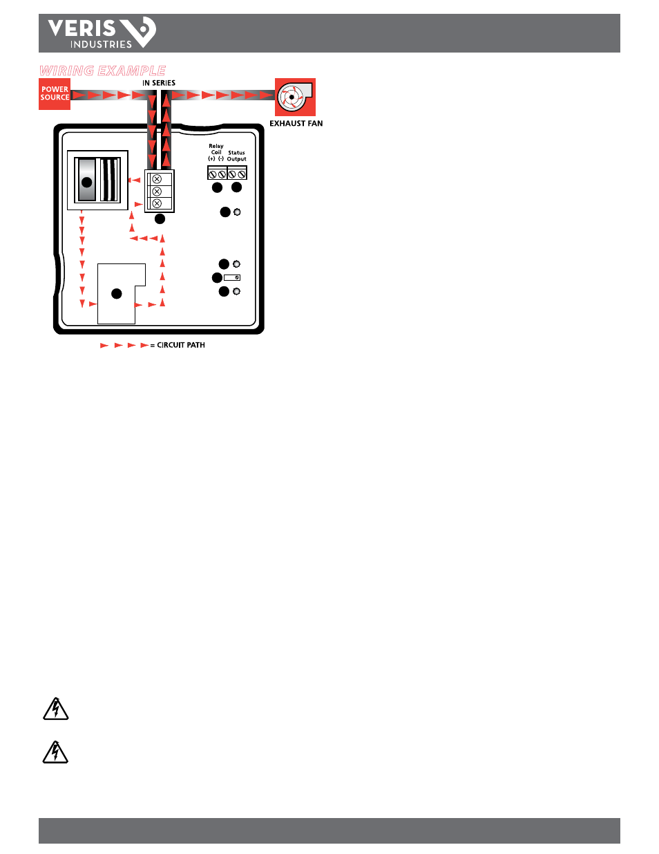
Wiring example
C
N.C.
N.O.
2
1
3
4
5
6
7
8
9
1.
Power Terminal Block:
Wire the H540NS/548NS in series with the motor using
these terminals. Choose N.O. or N.C.
2.
Current Sensor:
In-series current sensor for motor status.
3.
Relay:
Enables actuation of circuit by a control system.
4.
Relay Coil Terminal Blocks:
Wire the output signal from the control panel to
actuate the relay. 24 VAC/DC; 36 mA nominal.
5.
Status Terminal Blocks:
Wire the status input back to the control panel.
6.
Relay Status LED:
For positive indication of energized coil.
7.
Status Open LED:
Indicates that the current is below the trip point and the status
contact is open (used to calibrate the current switch in H548NS models only).
8.
Current Switch Set-Point Screw:
Used to adjust the point in the current range at
which the current switch will change states (used to calibrate the current switch
in H548NS models only).
9.
Status Closed LED:
Indicates that the current is above the trip point and the
status contact is closed (used to calibrate the current switch in H548NS models
only).
CAUTION!
Do not rely on status indicators to determine whether or not the relay contacts are
connected to a power source. Doing so may result in injury or death from electrical
shock.
If the connections to the unit are made through more than one metallic conduit, bond
the conduits to prevent the hazard of electric shock. A bonding plate is available (Veris
part AH10).