Dimensions, Installation – Veris Industries H421 Install User Manual
Page 2
Z201200-0G
Page 2 of 4
©2013 Veris Industries USA 800.354.8556 or +1.503.598.4564 / [email protected] 06132
Alta Labs, Enercept, Enspector, Hawkeye, Trustat, Aerospond, Veris, and the Veris ‘V’ logo are trademarks or registered trademarks of Veris Industries, L.L.C. in the USA and/or other countries.
Other companies’ trademarks are hereby acknowledged to belong to their respective owners.
Installation Guide
Current Sensors
H421/H421SP
TM
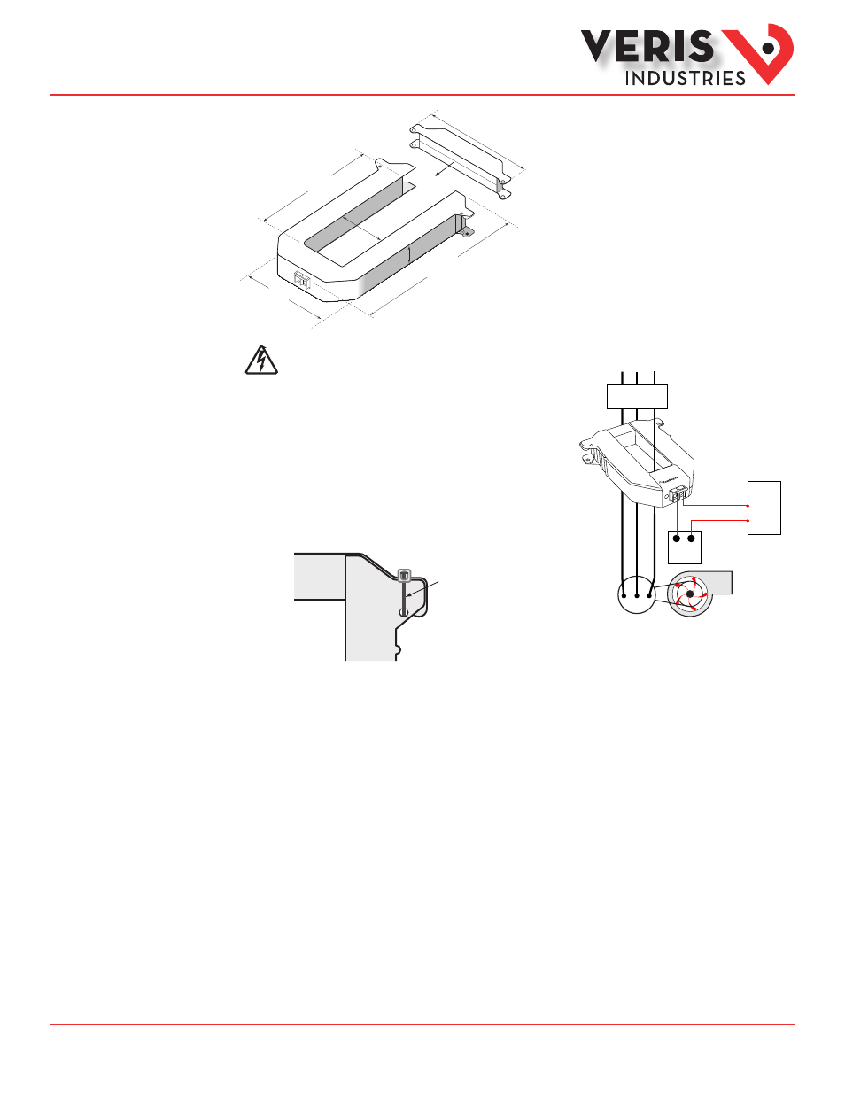
Dimensions
Disconnect and lock out power to the enclosure containing the conductor to be
monitored.
1. Choose a location for the sensor. The monitored conductor must pass
through the center window, and the sensor must be at least ½” (13 mm)
from any uninsulated conductors. Determine cable routing for the controller
connection, allowing the sensor to reach the conductor.
2. Wire the output connections between the sensor and the controller
(4-20 mA).
3. Snap the sensor over the conductor to be monitored.
4. Secure I-bar to main body of sensor with wire ties or other securing method.
Wire tie
5. Secure the enclosure and reconnect power.
6. Scale the sensor range, then scale the controller software to match the sensor’s output (see Scaling section).
Installation
4.90”
(125 mm)
5.50”
(140 mm)
2.45”
(62mm) 1.13”
(29 mm)
8.13”
(207 mm)
5.92”
(151 mm)
Motor
DIGITAL CONTROL
12-30VDC
Power Supply
AI
–
+
+
–
Fan or Pump
421
CONTACTOR