Veris Industries H970LCB Install User Manual
Installation guide, Wiring example, Dimensions
6%2)3
CURRENT MONITORING
INSTALLATION GUIDE
Z203253-0D
PAGE 1
©2009 Veris Industries USA 800.354.8556 or +1(0)503.598.4564 / [email protected]
07091
Alta Labs, Enercept, Enspector, Hawkeye, Trustat, Veris, and the Veris ‘V’ logo are trademarks or registered trademarks of Veris Industries, L.L.C. in the USA and/or other countries.
Split-Core Low Current 4-20mA & 0-10VDC
DC Current Transducer
Installer’s Specifications
Technology
Open loop Hall effect
Amperage Range
0 to 20/40/80 ADC (slide switch selectable)
Sensor Supply Voltage
15 to 30VAC/DC
Supply Current
35mA max.
Isolation
600VAC rms
Temperature Range
-15° to 60°C (5° to 140°F)
Humidity Range
10-90% RH non-condensing
Output
4-20mA and/or 0-10VDC
Accuracy
±3% F.S. combined linearity, hysteresis, and repeatability
The product design provides for basic insulation only.
)";"3%0'&-&$53*$4)0$, &91-04*0/ 03"3$'-"4)
t 'PMMPXTBGFFMFDUSJDBMXPSLQSBDUJDFT
4FF/'1"&JOUIF64" PSBQQMJDBCMFMPDBMDPEFT
t 5IJTFRVJQNFOUNVTUPOMZCFJOTUBMMFEBOETFSWJDFECZRVBMJmFEFMFDUSJDBMQFSTPOOFM
t 3FBE
VOEFSTUBOEBOEGPMMPXUIFJOTUSVDUJPOTCFGPSFJOTUBMMJOHUIJTQSPEVDU
t 5VSOPõBMMQPXFSTVQQMZJOHFRVJQNFOUCFGPSFXPSLJOHPOPSJOTJEFUIFFRVJQNFOU
t 6TFBQSPQFSMZSBUFEWPMUBHFTFOTJOHEFWJDFUPDPOmSNQPXFSJTPõ
%0/05%&1&/%0/5)*4130%6$5'0370-5"(&*/%*$"5*0/
t 0OMZJOTUBMMUIJTQSPEVDUPOJOTVMBUFEDPOEVDUPST
'BJMVSFUPGPMMPXUIFTFJOTUSVDUJPOTXJMMSFTVMUJOEFBUIPSTFSJPVTJOKVSZ
%"/(&3
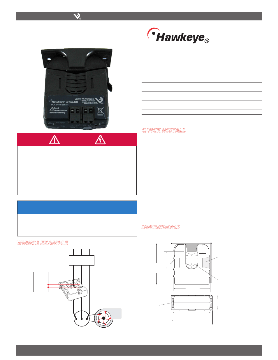
Wiring ExamplE
H970LCB
970LCB
DimEnsions
/05*$&
t 5IJTQSPEVDUJTOPUJOUFOEFEGPSMJGFPSTBGFUZBQQMJDBUJPOT
t %POPUJOTUBMMUIJTQSPEVDUJOIB[BSEPVTPSDMBTTJmFEMPDBUJPOT
t 5IFJOTUBMMFSJTSFTQPOTJCMFGPSDPOGPSNBODFUPBMMBQQMJDBCMFDPEFT
t .PVOUUIJTQSPEVDUJOTJEFBTVJUBCMFmSFBOEFMFDUSJDBMFODMPTVSF
quick install
Disconnect and lock out power to the conductor to be monitored.
1.
Choose a location for the sensor. The monitored conductor must pass through the
2.
iris, and the sensor must be at least 1/2” from any uninsulated conductors.
Install the adjustable mounting bracket to the back of the enclosure using the
3.
included screws.
Connect 15-30VAC/DC to the terminals marked Power (+) and Gnd (-).
4.
Wire the output (mA or VDC) connections between the sensor and the controller.
5.
Snap the sensor over the conductor to be monitored and clip the assembly to the
6.
mounting bracket.
Set the field-selectable switch to the desired amperage level (see page 2).
7.
Fan or Pump
CONTROLLER
4-20mA DC
Analog
Input
MOTOR
CONTACTOR
Removable Mounting Bracket
Self-gripping
Iris
1.0”
(25 mm)
0.8”
(21 mm)
1.1”
(26 mm)
3.1”
(79 mm)
2.8”
(70 mm)
Ø = 0.3”
(8 mm)
1.4”
(36 mm)
2.5”
(64 mm)
3.0”
(76 mm)
Bracket can be mounted
on either side for added
installation flexibility.
Use DIN Rail
Mounting clip
(Veris part
number AH01) to
mount on stan-
dard DIN rail.