Caution, Installation guide, Product overview – Veris Industries H800 Install User Manual
Page 2: Troubleshooting
Z201984-0G
PAGE 2
©2012 Veris Industries USA 800.354.8556 or +1.503.598.4564 / [email protected]
12121
Alta Labs, Enercept, Enspector, Hawkeye, Trustat, Veris, and the Veris ‘V’ logo are trademarks or registered trademarks of Veris Industries, L.L.C. in the USA and/or other countries.
TM
INSTALLATION GUIDE
H800
PRODUCT OVERVIEW
The H800 is a current-sensitive switching device that monitors current (amperage) in
the conductor passing through it. A change in amperage in the monitored conducter
that crosses the switch threshold will cause the resistance of the status output to
change state, similar to the action of a mechanical switch. The threshold is fixed at
0.2 A or less. The status output is suitable for connection to building controllers or
other appropriate data acquisition equipment operating at up to 30 volts. The H800
requires no external power supply to generate its output.
TROUBLESHOOTING
Problem
Solution
No Reading at Controller
• Check for control voltage at sensor (<30 V)
• Check for amperage in monitored conductor (>0.25 A)
DANGER: 5A CTs can present hazardous voltages.
Install CTs in accordance with manufacturer's instructions.
Terminate the CT secondary before applying current.
H68xx‑5A CT
> 200 A (Sensor max.)
CAUTION
RISK OF EQUIPMENT DAMAGE
• Derate the product’s maximum current for the number of turns
through the sensing window using the following formula.
Rated Max. Amps ÷ Number of Turns = Max. monitored Amps
e.g. : 100A ÷ 4 Turns = 25 Amps max. in monitored conductor
• Failure to follow these instructions can result in overheating
and permanent equipment damage.
< 0.25 A (Sensor Min.)
0.5A
4x
0.1A
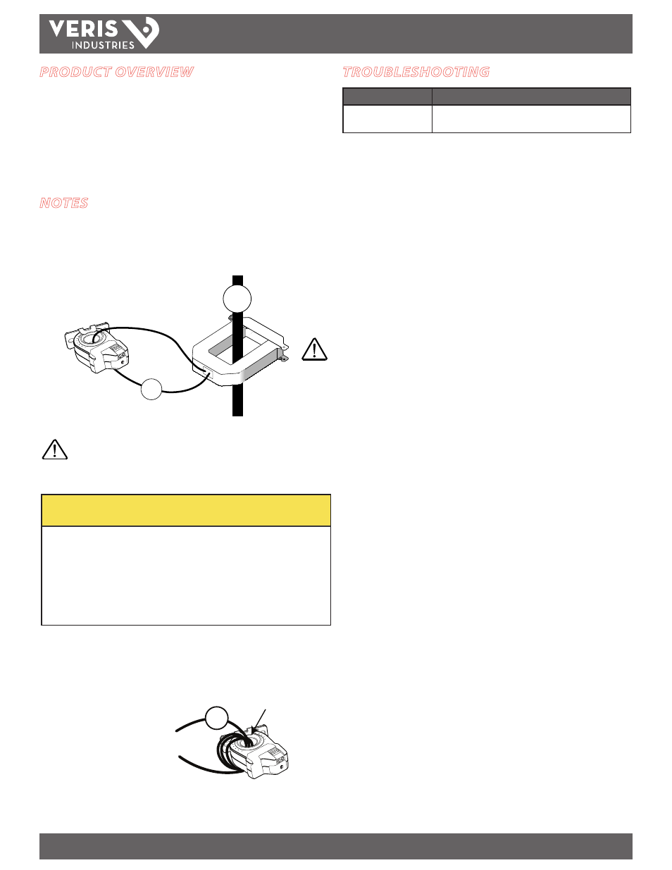
NOTES
For load currents greater than sensor maximum rating:
Use a 5 Amp (H68xx series) Current Transformer (CT) as shown. This technique can be
combined with wrapping (see below) to add range for a low current load on a high
current source.
For load currents less than sensor minimum rating:
Wrap the monitored conductor through the center window and around the sensor
body to produce multiple turns. This increases the current measured by the
transducer.
Program the controller to
account for the extra turns,
e.g., if four turns pass through
the sensor (as shown), then
divide the normal controller
reading by 4.
240A
300A:
5A
4A
250 A
4.2 A