Veris Industries H800NC Install User Manual
Danger, 800nc, Notice
TM
CURRENT MONITORING
INSTALLATION GUIDE
Z201981-0C
PAGE 1
©2013 Veris Industries USA 800.354.8556 or +1.503.598.4564 / [email protected]
03132
Alta Labs, Enercept, Enspector, Hawkeye, Trustat, Aerospond, Veris, and the Veris ‘V’ logo are trademarks or registered trademarks of Veris Industries, L.L.C. in the USA and/or other countries.
Solid-Core, Normally Closed Current Switch,
Fixed Trip Point
HAZARD OF ELECTRIC SHOCK, EXPLOSION, OR ARC FLASH
• Follow safe electrical work practices. See NFPA 70E in the USA, or applicable local codes.
• This equipment must only be installed and serviced by qualified electrical personnel.
• Read, understand and follow the instructions before installing this product.
• Turn off all power supplying equipment before working on or inside the equipment.
• Use a properly rated voltage sensing device to confirm power is off.
DO NOT DEPEND ON THIS PRODUCT FOR VOLTAGE INDICATION
• Only install this product on insulated conductors.
Failure to follow these instructions will result in death or serious injury.
A qualified person is one who has skills and knowledge related to the construction and
operation of this electrical equipment and the installation, and has received safety
training to recognize and avoid the hazards involved.
NEC2009 Article 100
No responsibility is assumed by Veris Industries for any consequences arising out of the
use of this material.
DANGER
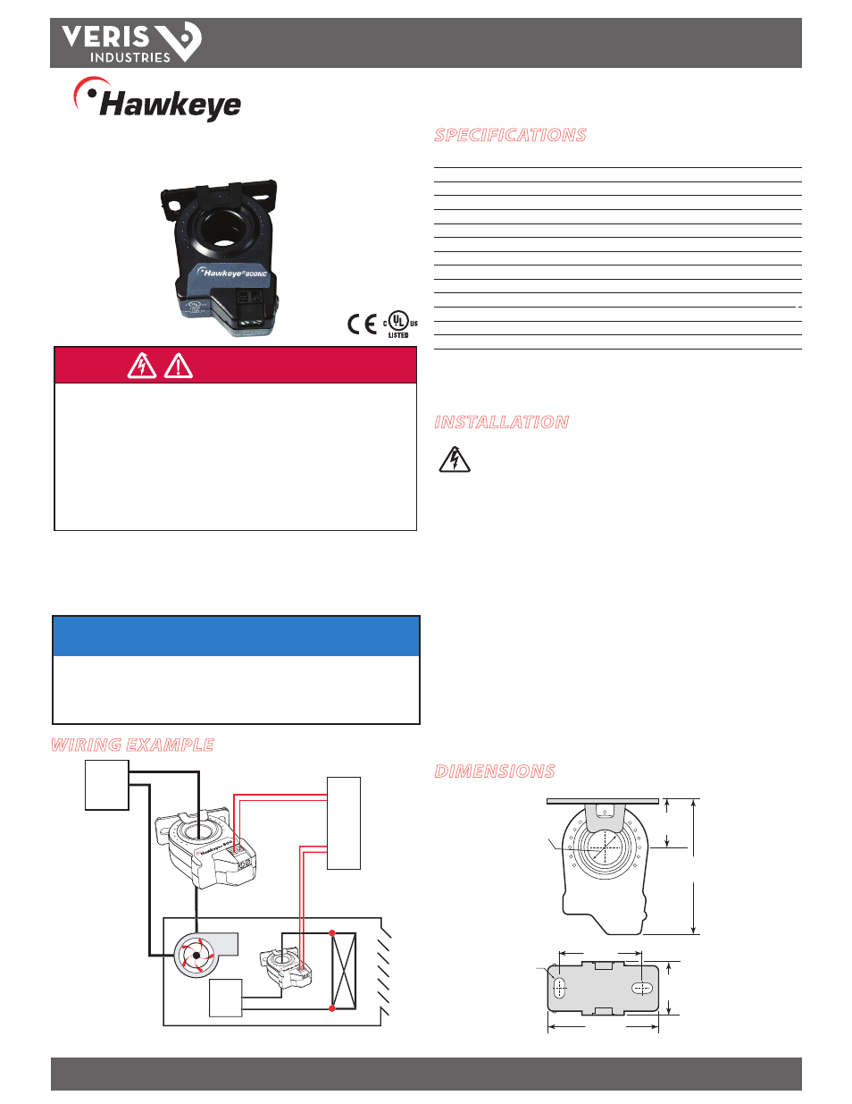
WIRING EXAMPLE
TM
800NC
DIMENSIONS
NOTICE
• This product is not intended for life or safety applications.
• Do not install this product in hazardous or classified locations.
• The installer is responsible for conformance to all applicable codes.
• Mount this product inside a suitable fire and electrical enclosure.
0 0.7"
(18 mm)
0.4” x 0.2”
Slot (x2)
2.8"
(71 mm)
1.7
(43 mm)
2.3"
(58 mm)
1.1"
(27 mm)
0.9"
(23 mm)
Removable/Adjustable Mounting Bracket
POWER
SOURCE
POWER
SOURCE
BUILDING AUTOMATION
CONTROLLER
UNIT VENT HEATER
DI
DI
SPECIFICATIONS
Sensor Power
5-30VDC, permanently connected
Amperage Range
0.5 - 200A Continuous
Status Output Ratings
N.C. 0.1A@30VDC not polarity sensitive
Insulation Class
600VAC RMS (UL), 300VAC RMS (CE)
Setpoint
Fixed at 0.5 A max. (60 Hz)
Frequency
50/60 Hz
Temperature Range -15° to 60°C (5° to 140°F)
Humidity Range
10-90% RH non-condensing
Off State Resistance
34µA@5VDC, 200µA@30VDC
On State Resistance
1.9VDC (max.)@0.1A
Terminal Block Wire Size
14 to 24 AWG (2.1 to 0.2 mm
2
)
Terminal Block Torque
3.5 to 4.5 in-lb (0.4 to 0.5 N-m)
Agency Approvals
UL508, CE: EN61010-1
Installation Category
Cat. III, pollution degree 2
For CE compliance, conductor shall be insulated according to IEC 61010‑1.
Listed for use with 75°C insulated conductors.
INSTALLATION
Disconnect and lock out power to the enclosure
containing the conductor to be monitored.
1. Locate a mounting surface for the removable mounting bracket that will allow the
monitored conductor to pass through the center window when it is installed and
that will keep the device at least ½” (13 mm) from any uninsulated conductors.
Determine cable routing for the output connection, allowing wiring to reach the
mounting location.
2. Drill holes to mount the bracket to the chosen surface using the included screws.
3. Wire the output connections and relay between the sensor and the controller
(solid-state contact).
4. Wire the sensor to external power supply.
5. Route the conductor through the sensor’s center window and clip the assembly to
the mounting bracket.
6. Secure the enclosure and reconnect power.