Current monit oring, Dimensional drawings, Application/wiring diagram – Veris Industries H721 SERIES Datasheet User Manual
Page 2: Ordering information, Accessories, Model amperage range sensor output housing ul ce
current monit
oring
800.354.8556
+1 503.598.4564
www.veris.com
MODEL
AMPERAGE RANGE
SENSOR OUTPUT HOUSING
UL
CE
H721LC
0 - 10/20/40A
4-20mA DC
Solid-Core
n
n
H721HC
0 - 50/100/200A
Solid-Core
n
n
H921
0 - 30/60/120A
Split-Core
n
1
n
H721LC/H721HC
H921
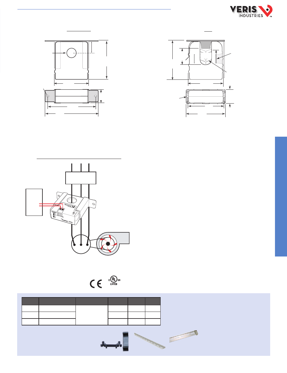
DIMENSIONAL DRAWINGS
* Terminal block may extend up to 1/8” over the height dimensions shown.
** Slide switch may extend up to 1/4” over the height dimensions shown.
APPLICATION/WIRING DIAGRAM
Monitoring Fan /Pump Motors for Positive Proof of Flow
ORDERING INFORMATION
1
Listed for use on 75°C insulated conductors.
Note: For 10-80 Hz applications, see the H720 VFD sensor.
0.2” x 0.15”
slot (2x)
1.1" *
(27 mm)
2.8"
(68 mm)
0 0.7"
(19 mm)
0.9"
(23 mm)
3.0" **
(75 mm)
Removable/Adjustable Mounting Bracket
3.8"
(95 mm)
4.2"
(106 mm)
Removable Mounting Bracket
Self-gripping Iris
1.0”
(25 mm)
0.8”
(21 mm)
1.1”
(26 mm)
**3.1”
(79 mm)
2.8”
(70 mm)
Ø 0.3”
(8 mm)
1.4”*
(36 mm)
2.5”
(64 mm)
3.0”
(76 mm)
Bracket can
be mounted
on three sides
for added
installation
flexibility.
Fan or Pump
CONTACTOR
DDC CONTROLLER
AI
Motor
ACCESSORIES
DIN Rail Clip Set (AH01)
DIN Rail (AV01) and DIN Stop Clip (AV02)
AH01
AV01
AV02
E212445
E150462
HQ0001762.B 01131