Veris Industries H934 Install User Manual
H934, Notice, Danger
VERIS INDUSTRIES
™
CURRENT MONITORING
INSTALLATION GUIDE
Z201186-0F
PAGE 1
©2010 Veris Industries USA 800.354.8556 or +1.503.598.4564 / [email protected]
04102
Alta Labs, Enercept, Enspector, Hawkeye, Trustat, Veris, and the Veris ‘V’ logo are trademarks or registered trademarks of Veris Industries, L.L.C. in the USA and/or other countries.
Split-Core Current Switch, Auto Calibrating,
with Relay and Nuisance Reduction Feature
For VFD Applications
HAZARD OF ELECTRIC SHOCK, EXPLOSION, OR ARC FLASH
• Follow safe electrical work practices.
See NFPA 70E in the USA, or applicable local codes.
• This equipment must only be installed and serviced by qualified electrical personnel.
• Read, understand and follow the instructions before installing this product.
• Turn off all power supplying equipment before working on or inside the equipment.
• Use a properly rated voltage sensing device to confirm power is off.
DO NOT DEPEND ON THIS PRODUCT FOR VOLTAGE INDICATION
• Only install this product on insulated conductors.
Failure to follow these instructions will result in death or serious injury.
DANGER
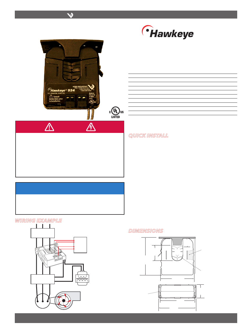
Wiring ExamplE
H934
TM
934
DimEnsions
NOTICE
• This product is not intended for life or safety applications.
• Do not install this product in hazardous or classified locations.
• The installer is responsible for conformance to all applicable codes.
• Mount this product inside a suitable fire and electrical enclosure.
quick install
Disconnect and lock out power to the conductor to be monitored.
1.
Choose a location for the sensor. The monitored conductor must pass through
2.
the iris, and the sensor must be at least 1/2” from any conductors as enclosure can
reach 87°C during operation (at 60°C ambient temperature).
Mount the H934 on the load side output conductor of the Variable Frequency
3.
Drive.
Install the adjustable mounting bracket to the back of the enclosure using the
4.
included screws.
Wire the status and relay coil connections between the sensor and the controller.
5.
Connect the relay to the contactor.
6.
Snap the sensor over the conductor to be monitored and clip the assembly to the
7.
mounting bracket on one of the three sides.
Perform the Setup (see page 2).
8.
Fan or Pump
CONTACTOR
DIGITAL CONTROL
Motor
DI
(Status)
DO
(Relay
Coil)
CONTROL
POWER
VFD
Installer’s Specifications
Sensor Power
Induced from monitored current
Amperage Range
3.5 - 135A Continuous
Insulation Class
600VAC RMS (UL)
Frequency
34 to 75 Hz (belt loss indication); 20 to 34 Hz (on/off status)
Temperature Range
-15° to 60°C (5° to 140°F)
Humidity Range
10-90% RH non-condensing
Off Delay
0 sec to 2 min.
Terminal Block Maximum Wire Size
14 AWG
Terminal Block Torque (nominal)
4 in-lbs (0.45 N-m)
Relay
5A@250VAC, 30VDC
Agency Approvals
UL 508 open device listing
Specification Note: For CE compliance, conductor shall be insulated according to IEC 61010‑1:2001,
Installation Category III or equivalent.
The product design provides for basic insulation only.
Removable Mounting Bracket
Self-gripping
Iris
1.0”
(25 mm)
0.8”
(21 mm)
1.1”
(26 mm)
3.1”
(79 mm)
2.8”
(70 mm)
Ø = 0.3”
(8 mm)
1.4”
(36 mm)
2.5”
(64 mm)
3.0”
(76 mm)
Bracket can be mounted
on either side for added
installation flexibility.
Use DIN Rail
Mounting clip
(Veris part
number AH01) to
mount on stan‑
dard DIN rail.